
Summary of Contents for Wazau TRM 1000
- Page 1 DR.-ING. GEORG WAZAU Mess- + Prüfsysteme GmbH Keplerstraße 12 > D-10589 Berlin > Germany > Fon +49-30-344 30 88(89), Fax +49-30-3441976 Web www.wazau.com, E-Mail info@wazau.com Manual TRIBOMETER TYPE TRM 1000 Rev. 02-2007...
-
Page 2: Table Of Contents
0. INTRODUCTION 1. CONNECTING CONTROL RACK, TEST RIG AND PC 1.1 C ..............................4 OMPONENTS 1.1.1 C ............................4 ONTROL 1.1.2 C ..............................6 OMPUTER 1.1.3 T ..............................6 1.1.4 E ........................... 8 LECTRICAL ONNECTIONS 2. CONTROL RACK 2.1 M OUTPUT ............................ - Page 3 4.6.3 F ....................... 44 URTHER BUTTONS AND ISPLAYS 4.6.4 C ........................44 ONTROLLER EMPERATURE 4.6.5 C ........................... 44 ONTROLLER ORCE 4.6.6 M ............................45 PTIONS 4.6.6.1 Settings..............................45 4.6.6.2 Autotuning Temperature / Normal Force ....................46 4.6.6.3 Lift Operation ............................46 4.7 A ............................
- Page 4 0. INTRODUCTION The tribometer serves for the investigation and simulation of friction and wear processes under sliding conditions. It can be operated for solid state friction without lubrication and for boundary lubrication with liquid lubricants. Thus both material and lubricant tests can be executed. According to the standard test principle a stationary test specimen (pin or disc) with a defined normal force is pressed against the surface of a rotary disc.
-
Page 5: Connecting Control Rack, Test Rig And Pc
Specification Strain collective Type of motion Sliding Mode of motion Continuous Normal force By means of a drive-spindle system adjustable from 5 – 1000 N Rotational speed From 0.1 to 3000 rpm steplessly adjustable Testing temperature From RT to 150 °C steplessly adjustable Tribological values Measured value FR –... -
Page 6: Components
1.1 Components 1.1.1 Control Rack The control rack incorporates the plug-in unit with all amplifiers and power supply for all modules, the drive controller, and the drive itself. The compressed air conditioning and the main power switch are located at the bottom of the control rack. Control Rack Slide-in unit of the control rack Page - 4... - Page 7 Main switch and compressed air conditioning Rear side of the control rack with connections for lead, drive, lift, heater, and compressed air (IN/OUT) Page - 5...
-
Page 8: Computer
Rear side of the control rack with removed rear wall to change fuses 1.1.2 Computer The USB measuring module and the RS 232/USB converter cable for data acquisition and controlling the test rig are connected to the computer. 1.1.3 Test Rig The test rig represents the mechanical measuring unit other add-in modules can be added to. - Page 9 Sensor Interface TEMPERATURE Type-K Thermocouple input for specimen pot and IR ring heater (if connected). FORCE Normal force sensor input. The sensor inputs are automatically identified by its coded plugs and assigned to the corresponding measuring ranges of the software. Plug in a sensor’s plug carefully to prevent the pins of the multi-pole plugs from bending which may cause a bad electrical contact or no contact at all.
-
Page 10: Electrical Connections
1.1.4 Electrical Connections Power supply: Three-phase current connection 3 x 400 V/50 Hz, plug: 5 x CEE plug, 5 x 32 A. If a FI risidual-current circuit-breaker is used, it must be suitable for applications for frequency inverters (suitable for type Fuses The conrol rack contains fuses on the rear side for he following loads: Drive... -
Page 11: Control Rack
2. Control Rack The following modules are located in the control rack: ■ Module OUTPUT ■ Module FORCE ■ Module WEAR ■ Module TORQUE ■ Module TEMPERATURE CONTROLLER ■ Moduel MOTORCONTROL (drive) ■ Module FORCE CONTROLLER ■ Module FRICTION FORCE (option) 2.1 Module OUTPUT The module OUTOUT connects the measuring channels to the computer by means of an USB interface. -
Page 12: Module Force
2.2 Module FORCE In order to achieve a precise measurement the normal force-amplifier has to be calibrated in an unloaded condition prior to the setup of the tribometer (offset adjustment). The calibration is done to eliminate influences on the sensor that may cause measuring errors such as the deadweight of the specimen pot or other parts. -
Page 13: Module Wear
2.3 Module WEAR Pushing the tracer „Wear Off“ on the software enables or disables the measuring channel „Wear“. If “Wear” is disabled the offset adjustment will not be conducted. The displacement sensor is secured against overloading by a limit switch. The alarm shuts down drive and heater if the displacement (wear) exceeds the maximum measuring range of the laser-optical displacement sensor or if the measuring system has an error. -
Page 14: Module Torque
2.4 Module TORQUE Pressing the tracer „Torque RMS“ on the software interface enables the root mean square (RMS) rectifier. In addition there is a 25 Hz low-pass enabled to disable interfering signals. The torque shaft is secured against overloading by a limit switch. The alarm shuts down drive and heater if the measured torque exceeds the maximum measuring range by 1 % (±... -
Page 15: Module Temperature
2.5 Module TEMPERATURE Control parameters and requested values are set on the software. The temperature controll cannot be changed manually as it is locked. The heater is secured against overloading by a limit switch. The alarm shuts down drive and heater if the temperature exceeds the maximum temperature range by 15°C or if the thermocouple is broken. -
Page 16: Module Motorcontrol
2.6 Module MOTORCONTROL Pushing the tracer „BLOCKING" on the software blocks the drive shaft. That way the operator can loosen or tighten the screws of the specimen adapter easier. The torque shaft is secured against overloading by a limit switch. The alarm enables the blocking function if the measured torque exceeds the maximum measuring range by 1% (±... -
Page 17: Module Force Controller
The controls of the air conditioning of the air-bearing spindle requires a pressure of 7 - 8 bar. The IMPORTANT! pressure has to be applied on the system spontaneously. A slow increase of the pressure leads to a malfunction of the switch thresholds so that the controls of the air conditioning won’t start. -
Page 18: Module Friction Force (Option)
2.8 Module FRICTION FORCE (option) Pressing the tracer „Torque RMS“ on the software interface enables the root mean square (RMS) rectifier. In addition there is a 25 Hz low-pass enabled to disable interfering signals. The friction force sensor is secured against overloading by a limit switch. The alarm shuts down drive and heater if the the measured friction force exceeds the maximum measuring range by 1 % (±... - Page 19 Sensor interface FRICTION FORCE Friction force sensor input The sensor inputs are automatically identified by its coded plugs and assigned to the corresponding measuring ranges of the software. Plug in a sensor’s plug carefully to prevent the pins of the multi-pole plugs from bending which may cause a bad electrical contact or no contact at all.
-
Page 20: Test Rig
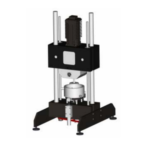
Lift jig with crane eyelets 3. Test Rig Drive Torque shaft Emergency stop switch Drive block Air-bearing spindle with Displacement (wear) measuring system Lift drive Specimen and module area Linear table Sensor interface Test Rig Normal force sensor Page - 18... -
Page 21: Mounting The Specimens
3.1 Mounting the specimens The test rig comprises the actual tribometer with all mechanical units. There are standard mountings for pin/disc or disc/disc tests. Depending upon the geometrical specimen pairing the lower specimen test specimen has to be installed in the specimen pot. Special mounting plate components can also be installed. To make sure that the friction areas of both specimens run flat one on the other when running disc/disc tests, the swash plate has to be used as the lower mounting. -
Page 22: Standard Specimen Pot For Lubricated Tests
3.2 Standard Specimen Pot for lubricated Tests The specimen pot is mounted on the support containing the heater. Prior to that the centrepin has to be mounted on the linear table with the tip up. That way the specimen pot is centred on the linear table. The specimen pot is resistant to corrosive media so that tests with corrosive lubricants can also be conducted. -
Page 23: Ball Holder / Pin Holder
3.3 Ball holder / Pin holder The pin holder fits pins of the diameter 6 mm, 8 mm, and 10 mm, with a length of 30 mm. The ball holder fits balls of a diameter 5 mm, 6 mm, 8 mm, and 10 mm. To change balls/pins unscrew the cover of the holder. -
Page 24: Disc Holder
Pin holder Pin-on-disc arrangement for lubricated and unlubricated tests. 3.4 Disc Holder To make sure that both discs are permanently in contact in the horizontal position a swash plate is mounted under the plate specimen. First mount the stops on the support und place the ball in the middle of the counterbore. Then place the mounted specimen with the swash plate on the support. -
Page 25: Mounting Of The Ring Heater (Option)
Clamping ring Slotted ring 3.5 Mounting of the Ring Heater (option) Let the drive block go up to the end switch in order to mount subsequently the specimen holder to the air-bearing spindle. To do that mount first the white insulation board on the tribometer support and centre it with the pin in the middle. After that install the pre-assembled specimen arrangement on the insulation board and mount to the tribometer support by means of the four screws. -
Page 26: Compressed Air Conditioning
Gas inlet Cover sides Ring heater Power supply connector Thermocouple 3.6 Compressed air conditioning The air conditioning represents the air supply of the air-bearing spindle. The compressed air is filtered and dried before getting into the air-bearing. The input pressure of the filter unit should be 7 – 8 bar. 7 bar should be adjusted on the filter controller unit using the manometer. -
Page 27: Tribometer Software
Pressure controller Membrane dryer Manometer Hand outlet Filter unit Filter units Compressed air inlet Compressed air outlet Air-bearing spindle 4. Tribometer Software The software mainly consists of three windows. The setup window gives an overview on the settings. On the control window the program execution can be set and observed. -
Page 28: Usb Serial Controller
• MCC DAQ, • TriboControl application software. 4.1.1 USB Serial Controller On installation the USB serial controller the driver to adapt the converter cable from the RS 232 interface to the USB interface is installed. Proceed as follows: 1. Insert the CD „Driver“ and „User’s Guide“ (Transfer Series) into the das CD/DVD ROM drive of your computer. 2. - Page 29 Picture 1 Picture 2 Picture 3 Picture 4 Picture 5 Picture 6 Page - 27...
- Page 30 Picture 7 7. Windows recognizes now the new hardware and starts the assistant to search new hardware (picture 7). 8. Start then the under „System Control“ the menu „Hardware“ and „Device Manager“ of the Windows operating system (picture 8). 9. On the „Device manager“ click on connections (COM and LPT, picture 9). Picture 8 Picture 9 10.
-
Page 31: Mcc Daq
4.1.2 MCC DAQ The software contains the driver fort he USB measuring module and is required to run the application software TriboControl. Proceed as follows: Connect the USB cable from the slide-in Module OUTPUT to the USB interface of the computer. 12. - Page 32 Execute the installation in accordance with the requests of the installation routine (pictures 11, 12, 13). Picture 11 Picture 12 Picture 13 Page - 30...
- Page 33 16. After the installation you may install different PDF documents of the manufacturer. Click the button Cancel to close the window (picture 14). After that click NO in order not to display the Readme file (picture 15). Picture 14 Picture 15 17.
-
Page 34: Tribocontrol
4.1.3 TriboControl The software TriboControl represents the actual program to control and measure. Proceed as follows: Insert the CD TriboControl into the CD/DVD-ROM drive of your computer. Start the file setup.exe in the directory Installer on the CD. The installation program installs the TriboControl Software and the LabVIEW 7.1 Runtime which needs to be installed on the system. - Page 35 20. Start the software using the software „Start/Programme/TriboControlV5/TriboControlV5“. Starting the software for the first time will require: To assign the COM-ports on the software. The software will start with the messages „Fehler Init Kraft COM (error Init Force COM)” etc. and “Gerät muss vor Softwarestart eingeschaltet werden! Software neu starten! (tribometer has to be turnt on before starting the software)“...
- Page 36 21. Push always the button OK and open on the software on the window „Control“ the window „Einstellungen“ (settings) under „Optionen“ (options) (picture 19). Now enter in the Device Manager the determined COM ports of the RS 232/USB converter cables in the corresponding fields.Push the button Übernehmen (accept) and quit the software TriboControl.
-
Page 37: Setup Window
4.2 Setup Window On this window in three sectors are displayed: measuring ranges, limits, test program with operating parameters and file settings. In each sector setting can be changed by pushing the Ändern button (change). That action opens an input window in which the desired parameters can be entered. -
Page 38: Measuring Settings And Limits - Subwindow
4.3 Measuring settings and limits - Subwindow In this window measuring settings and limits can be altered. Here limits of the measuring channels, friction radius and the length of the stroke can be set. Since some measuring channels may be engaged several times by sensor switching there is a selection field to choose from the possible measuring values of that channel. -
Page 39: Program Selection Subwindow
4.4 Program Selection Subwindow In sector Prüfmodus (testing mode) test programs can be created, saved or loaded. Different operation modes can be chosen from. The standard modes provided by any tribometer are Rotation (rotation), Rampen (ramps) and Oszillation (oscillation). Other modes require the corresponding add-on modules. They cannot be chosen until the module has been connected. -
Page 40: Mode Ramps
4.4.2 Mode Ramps In this program mode a set value of rotational speed increases within a defined period of time, is hold for a defined time and decrases within a defined period of time down to zero rpm. It is possible to enter 10 different ramps into the table. Each ramp can be repeatedly executed. - Page 41 Oscillation applies to a defined position or to the current position. If a position is defined (0 - 360°), this position will be approached at low speed before oscillations actually starts. When an oscillation being executed is aborted by the software the segment of circle will be not left.
-
Page 42: Mode Linear Oscillation
4.4.4 Mode Linear Oscillation In this mode a rotating movement is transformed into a translational movement on a linear way by means of the Linear Oscillation Module. On this mode only the rotational speed can be set. The max. value of the rotational speed is 300 rpm, corresponding to 5 Hz. -
Page 43: Data File Setup Window
4.5 Data file Setup Window In order to generate a measuring file and a protocol file a path has to be named and the disk symbol enabled (it is enabled if no cross appears). The measuring values are binary saved in a *.trm file (tribometer measured values). They can be viewed using the Analysis tool. -
Page 44: Control Window
4.6 Control Window On this window test programs can be started and measured and calculated data be viewed. Moreover with the heater installed temperature and normal force can be set. If all entries on the setup window are enabled and the wear (displacement) sensor is within its working range, a test program can started by pushing the “Starten (start)”... -
Page 45: Numerical Display
The values friction coefficient and friction force at rotating movement are calculated values satisfying the following equation: Friction coefficient at rotating movement: µ = M * 1000 / F with µ = friction coefficient [-] M = friction torque [Nm] = normal force [N] r = radius [mm] Friction coefficient at linear movement:... -
Page 46: Further Buttons And Displays
4.6.3 Further Buttons and Displays There are three LEDs for Overload (OVL), Limit (LMT) and program execution (PROG). If an overload occurs the button “Reset” has to be enabled to enable the drive. The button „Blocking“ blocks the drive to change the specimens. -
Page 47: Menu Options
4.6.6 Menu Options The menu point „Optionen (options)” of the runtime menu allows the user to enter settings, save surface settings, travel to defined positions and open the Analysis Tool. 4.6.6.1 Settings By means of this menu point language, COM connections and plots can be chosen or assigned respectively. Once the COM device is connected to the computer the assignment of the COM connection is displayed on the device manager. -
Page 48: Autotuning Temperature / Normal Force
“Werte schreiben (enter values)” allows the user to enter manually PID parameters. Autotuning for normal force should not be done until the user has contacted a Wazau specialist. The parameters for normal force and temperature control are set ex works, providing an optimized setting for most applications. -
Page 49: Analysis Window
4.7 Analysis Window By means of this tool the saved binary data is visualized and converted into other formats. To open a *.trm file choose “Datei öffnen (open file)” from the runtime menu. Then x-axis and y-axis have to be assigned. It is possible to display two y-axis over the time or the glide way. -
Page 50: Recipe Controller
4.8 Recipe Controller As alternative to the control program the controlling can be executed in recipe steps. Operating parameters can be entered in a list that is executed sequently. A step is considered executed if the desired operating parameter has been reached, e.g. - Page 51 By means of the button „Bearbeiten (edit)” in a sub window recipe steps can be altered, added or deleted. The button “Übernehmen (accept)” accepts an altered program. “Abbrechen (abort)” will reject the changes. Other abort conditions can be set to end the recipe program safely. On the left side the edit window shows a selection of possible recipe Steps.
- Page 52 The different recipe steps are explained hereafter. Rotation Setting direction of rotation, rotational speed, and rotational speed ramp. On changing the direction of movement of the drive the rotational speed ramp goes down to zero. Then it speeds on the other direction at the set rotational speed ramp. Oscillation In the oscillation mode the rotational speed and an oscillation angle is set.
- Page 53 Vibration The vibration is generated by an overlayed sinoidal rotational speed fluctuation. If an amplitude bigger than zero is set vibration is enabled. If zero is entered vibration is disabled. Temperature Temperature Steps are considered finished if the current temperature differs from the desired temperature by no more than 1°C.
- Page 54 Hold This recipe step inserts a holding time in between two steps. That can be done by entering a value for time or gliding way. Time can be entered in minutes or hours. This command ends the recipe program. That means saving the measured values is finished, normal force and rotational speed have a value of zero, the heater is turnt off.
-
Page 55: Starting A Test
5. Starting a Test 5.1 Turning on and off Turning on: 1. Turn on the computer and load Windows XP completely. 2. Turn on the main power switch on the control rack and start the software TriboControl after 5 seconds. 3. -
Page 56: Installing Specimens / Offset Adjustment
5.2 Installing specimens / Offset adjustment Installing the specimens Mount the specimens to the suitable jig/adapter such as specimen pot or specimen support. Mount the specimens to the specimen holder of the air-bearing spindle outside of the test rig. Mounting the specimen to the air-bearing spindle is only allowed if the compressed air is applied. -
Page 57: Setting Up The Wear Measuring System
6. Setting up the Wear Measuring System To adjust the wear measuring system the normal force has to be applied on the specimens so that they are pressed against each other. Let the control system adjust the normal force completely. That means the desired value is equal the actual value. - Page 58 Picture 5 LED State LED State - Functions Laser diode OFF Error or displacement sensor out of measuring range green No error or displacement sensor within measuring range yellow No error or displacement sensor within middle position of the measuring range Picture 6 LED State Functions...
-
Page 59: Linear Oscillation (Option)
7. Linear Oscillation (option) The linear oscillation contains two modules used in combination. There is the module air-bearing unit to measure friction force and the module linear oscillation to transform the rotary movement into a linear movement. Setting up the test parameters such as normal force and rotational speed as well as setting up the wear measurement is done analog to the other modules as specimen pot and specimen support. -
Page 60: Linear Oscillation
7.1 Linear Oscillation The module is composed of an adjustable eccentric which transforms the rotary movement into a linear movement, moving the ball-pin carrier (option) in a linear (translational) way. The max. amplitude of the Linear Oscillation is ± 10 mm Adapter Linear Oscillation... -
Page 61: Adjusting The Amplitude
7.1.1 Adjusting the Amplitude 1. Turn the eccentric until the adjustment screw inside the eccentric opening becomes visible (picture 1, 2). 2. The adjustmen screw can be adjusted using a socket wrench. 3. If the amplitude adjusted before is not known turn the socket screw all the way to the right. 4. -
Page 62: Assembly Of The Linear Oscillation
7.1.2 Assembly of the Linear Oscillation 1. Mount the ball-pin carrier to the linear oscillation. Fix a ball or a pin to the carrier (picture 3). The scope of delivery provides a 10 mm ball holder. 2. On the software menu „Optionen (options)” go to „Position anfahren (travel to position)“. Press the button “Anfahren (travel)”... -
Page 63: Disassembly Of The Linear Oscillation
Groove Eccentric Picture 6 Picture 7 Fixing screws 7.1.3 Disassembly of the Linear Oscillation On the software menu „Optionen (options)” go to „Position anfahren (travel to position)“. Press the button “Anfahren (go to)” and close the window (picture 4). The drive moves now the the air-bearing spindle to a defined position in order to assemble or disassemble the linerar oscillation. -
Page 64: Air-Bearing Unit
7.2 Air-bearing Unit The air-bearing unit is composed of a linear air-bearing supporting the specimen carrier, and a friction force sensor. By means of a leaf spring the linear air-bearing is connected to the friction force sensor. Only use the air-bearing unit for tests if sensor plug and compressed air plug connection are connected to the test rig and the compressed air conditioning is complete. -
Page 65: Assembly Air-Bearing Unit
7.2.1 Assembly Air-bearing Unit 10. Mount carefully the air-bearing unit on the support of the tribometer (picture 8). In doing so move the air-bearing unit carefully by means of the handlebars. 11. Tighten the air-bearing unit to the linear table (support) of the tribometer by means of the fixing screws. 12. -
Page 66: Four-Ball Apparatus (Option)
8. Four-Ball Apparatus (option) By means of the four-ball apparatus friction mechanisms on loaded balls until welding can be investigated. The diameter of the four balls is 12.7 mm each. The applied load may range to the max. measuring range of the tribometer. The mode of motion on this module is rotation. -
Page 67: Mounting Ball Carrier
8.1 Mounting Ball Carrier Place the three balls into the carrier and tighten the unit by means of the nut. Assemble carefully the nut with the unit using both open-end wrenches (picture 10). To make sure that all four balls are in permanent contact in a horizontal position, a ball is mounted under the ball support. -
Page 68: Assembly Ball Holder
Picture 12 8.2 Assembly Ball Holder Place the ball into the carrier and tighten the unit by means of the nut. Assemble carefully the nut with the ball holder using the open-end wrench (picture 13). Mount the ball holder to the air-bearing spindle of the tribometer (picture 14). Picture 13 Ball holder Ball... -
Page 69: Specimen Dimensions
9. Specimen Dimensions Specimen disc for specimen holder (air-bearing spindle) Page - 67... - Page 70 Specimen disc for swash plate Page - 68...
- Page 71 Specimen disc for air-bearing unit (linear oscillation) Page - 69...
Need help?
Do you have a question about the TRM 1000 and is the answer not in the manual?
Questions and answers