
Related Manuals for RFE DS Series

Summary of Contents for RFE DS Series
-
Page 1: Indice
USER MANUAL - TRANSMITTER DS SERIES - 30 - 50 - 100 - 500 - 1000W USER MANUAL TRANSMITTERS DS SERIES 30|50|100|300|500|1000W Rev 1.3... -
Page 2: Table Of Contents
USER MANUAL - TRANSMITTER DS SERIES - 30 - 50 - 100 - 300 - 500 - 1000W Index ....................Indice Introduction & general information structure ............4 Hazardous Voltage Warning ................4 General Safety Recommendations ..............5 Document structure .................. - Page 3 USER MANUAL - TRANSMITTER DS SERIES - 30 - 50 - 100 - 500 - 1000W DB25 and DB9 pinout ..................Appendix A Touch screen calibration ................. Appendix B Upgrade Firmware ..................Appendix C Log-event and Alarms list ................Appendix D Web Page Control-SNMP .................
-
Page 4: Introduction & General Information Structure
USER MANUAL - TRANSMITTER DS SERIES - 30 - 50 - 100 - 300 - 500 - 1000W Introduction & general information structure This manual contains all informa on for installa on and maintenance of DS transmi ers and is divided into two parts: the fi rst concerning operator that has to use equipment, the other concerning maintenance technicians. - Page 5 USER MANUAL - TRANSMITTER DS SERIES - 30 - 50 - 100 - 500 - 1000W General Safety Recommendations All work on transmi er system as well as installed units, e-g- the VHF/FM transmi er, may only be carried out by trained personnel capable of iden fying dangerous situa ons or condi ons.
- Page 6 USER MANUAL - TRANSMITTER DS SERIES - 30 - 50 - 100 - 300 - 500 - 1000W Warning notices in this Manual A en on must be paid to important no ces contained in this manual. They are labelled as follows:...
- Page 7 USER MANUAL - TRANSMITTER DS SERIES - 30 - 50 - 100 - 500 - 1000W First aid Rev 1.3...
-
Page 8: Document Structure
USER MANUAL - TRANSMITTER DS SERIES - 30 - 50 - 100 - 300 - 500 - 1000W Document structure This document contains all the technical informa on rela ng to the transmi ers of Series DS. In the fi rst part we have all the technical specifi ca ons, followed by direc ons for the fi... -
Page 9: Introduction
USER MANUAL - TRANSMITTER DS SERIES - 30 - 50 - 100 - 500 - 1000W Introduction The transmi er DS is designed with all the latest technologies, such as high effi ciency using the latest genera on LDMOS transistor and high effi ciency power supplies. We used a modern interface and performance using a color display with touch screen, with easy management so ware and easy to use. -
Page 10: Features
USER MANUAL - TRANSMITTER DS SERIES - 30 - 50 - 100 - 300 - 500 - 1000W The transmi er is accommodated in a 19“ chassis, 2-HU height. All opera on and display elements are arranged on the front panel. The opera ng values are read from the LCD colour display with touch screen. -
Page 11: Technical Specifications
USER MANUAL - TRANSMITTER DS SERIES - 30 - 50 - 100 - 300 - 500 - 1000W Technical Specifi cations GENERAL MULTIPLEX OPERATION Power Output: 50W (typ. 55W), 100W (typ. 110W), 300W Composite Input Impedance: 2 Kohm unbalanced. Composite Input Level: DS series -6 to +18 dBm (typ. -
Page 12: Installation And Use
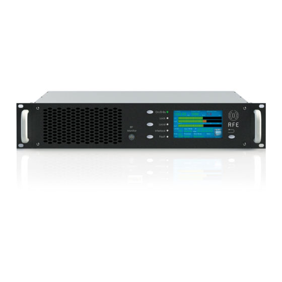
USER MANUAL - TRANSMITTER DS SERIES - 30 - 50 - 100 - 500 - 1000W Installation and Use Front panel Fig. 2: DS30-50-100-300-500-1000 Front view The front panel has fi ve LEDs that indicate the status of the transmi er, and are: ON/ST.BY... -
Page 13: Rear Panel
USER MANUAL - TRANSMITTER DS SERIES - 30 - 50 - 100 - 300 - 500 - 1000W Rear panel Fig. 3: DS30-50-100-300-500-1000 Rear view On the rear panel connectors are located as follows: Input Mains with power switch RF out... -
Page 14: Operating Instructions
USER MANUAL - TRANSMITTER DS SERIES - 30 - 50 - 100 - 500 - 1000W Operating instructions Local opera on of the DS30-50-100-300-500-1000 transmi er is actuated via 4 front panel keys and 5 led. Fig. 4: DS30-50-100-300-500-1000 Transmi er Front Panel... -
Page 15: Rf On/Off Switching
USER MANUAL - TRANSMITTER DS SERIES - 30 - 50 - 100 - 300 - 500 - 1000W All these Led and bu ons, integrate the capabili es of the LCD, to understand the status of the transmi er more clearly without access to the naviga on menu. -
Page 16: Fault/Reset Key
USER MANUAL - TRANSMITTER DS SERIES - 30 - 50 - 100 - 500 - 1000W Fault/Reset key Fault LED If a failure in the device occurs, the red Fault LED is on or blinking. Reset key For clear a failure, push the Fault/Reset key and the LED will be off . If the LED remain On or blinking the alarm persist. -
Page 17: Installation
USER MANUAL - TRANSMITTER DS SERIES - 30 - 50 - 100 - 300 - 500 - 1000W Installation Unpacking The package contains: • 1 DS Transmi er • 1 CD-ROM with the User Manual • 1 Mains power cable •... -
Page 18: Quick Start
USER MANUAL - TRANSMITTER DS SERIES - 30 - 50 - 100 - 500 - 1000W Quick start Before power on the transmi er, make sure that the it is connected to the antenna or to an adeguate power dummy load; connect the mains plug and turn on the transmi er. -
Page 19: Menu
USER MANUAL - TRANSMITTER DS SERIES - 30 - 50 - 100 - 300 - 500 - 1000W Menu Display and programming of the transmi er is through the LDC display touch screen. From the fi rst screen at power, as previously explained, can be accessed through the menu bu on to the submenu of the Audio, Frequency, Power, Se ng, Memories and Alarm. -
Page 20: Menu - Frequency
USER MANUAL - TRANSMITTER DS SERIES - 30 - 50 - 100 - 500 - 1000W Menu - Frequency By pressing the key frequency it accesses the rela ve panel for the se ng of the transmission frequency of the transmi er. -
Page 21: Menu - Power
USER MANUAL - TRANSMITTER DS SERIES - 30 - 50 - 100 - 300 - 500 - 1000W Menu - Power Fig. 8: Set power menu From the Power menu you can set the output power of the transmi er. In the screen are also displayed the Forward and Refl... - Page 22 USER MANUAL - TRANSMITTER DS SERIES - 30 - 50 - 100 - 500 - 1000W • Internal RDS (On/Off ) • Limiter Ac on (On/Off ) normally 84.2 kHZ (CCIR - Other Se ngs is available on request) • Preemphasis •...
- Page 23 USER MANUAL - TRANSMITTER DS SERIES - 30 - 50 - 100 - 300 - 500 - 1000W By clicking on the Change key the following panel appears, where it is possible change the input level: Fig. 10: Se ngs value for Audio Input level panel...
-
Page 24: Menu - Settings
USER MANUAL - TRANSMITTER DS SERIES - 30 - 50 - 100 - 500 - 1000W Fig. 12: Modula on mode se ngs Menu - Settings From the panel se ng will be possible to visualize the general readings of the system and change the confi... -
Page 25: Lan Configuration
USER MANUAL - TRANSMITTER DS SERIES - 30 - 50 - 100 - 300 - 500 - 1000W The displayed readings are: • Ipa 1-2-3: currents supplied by the power supplies; • 3v3/5v0/Serv: service voltages; • Vpa: Voltage power amplifi er, the voltage with which the RF is working;... - Page 26 USER MANUAL - TRANSMITTER DS SERIES - 30 - 50 - 100 - 500 - 1000W Clicking on each item in the list a se ngs panel opens, in which it is possible set the selected parameter. Fig. 15: Se ng LAN Ip Address Fig.
-
Page 27: Date/Time Settings
USER MANUAL - TRANSMITTER DS SERIES - 30 - 50 - 100 - 300 - 500 - 1000W Fig. 18: Se ng LAN DNS Fig. 19: Se ng Time server Date Time Setting In this panel it is possible to set Date and Time, a numeric keypad will allow us to enter numerical values, pressing enter will confi... -
Page 28: Db25 Settings
USER MANUAL - TRANSMITTER DS SERIES - 30 - 50 - 100 - 500 - 1000W DB25 Setting The transmi er can be controlled through the DB25 connector located in the rear pannel of the device. Clicking on the “DB25” key it is possible se ng: •... -
Page 29: Address Port Rs485
USER MANUAL - TRANSMITTER DS SERIES - 30 - 50 - 100 - 300 - 500 - 1000W Address port RS465 The “Addr” bu on allows to set the RS485 communica on port. Fig. 22: RS485 connector confi gura on panel 19kHz Output Amplitude This panel allows to change the amplitude of the pilot tone of 19kHz. -
Page 30: Power Reduction Settings
USER MANUAL - TRANSMITTER DS SERIES - 30 - 50 - 100 - 500 - 1000W The three parameters just men oned can be modifi ed through the following panel: Fig. 23: 19kHz Output Amplitude/Frequency devia on/Devia on phase se ngs Power Reduction Settings You can program the power reduc on in a determined me interval by confi... -
Page 31: Set Fsk/Id-Code Settings
USER MANUAL - TRANSMITTER DS SERIES - 30 - 50 - 100 - 300 - 500 - 1000W Set FSK/ID-Code Settings You can confi gure the IDCode from the panel se ng. By selec ng the indent with the slider you can select the number or le er and confi rm with the Enter key, the le er that staimo changing sara iden fi... -
Page 32: Audio C.o./Reserve Audio Source
USER MANUAL - TRANSMITTER DS SERIES - 30 - 50 - 100 - 500 - 1000W Audio C.O./Reserve audio source Fig. 27: Audio Change Over Se ngs Descrizione Audio change over. Options Status This item is a summary of some parameters, as AES/EBU, GSM. -
Page 33: Preset - Settings
USER MANUAL - TRANSMITTER DS SERIES - 30 - 50 - 100 - 300 - 500 - 1000W Preset - Settings From this panel you can enter in the se ng of the preset of the transmi er, in total there are 6 presets to se ng. - Page 34 USER MANUAL - TRANSMITTER DS SERIES - 30 - 50 - 100 - 500 - 1000W Fig. 30: Presets panel memory currently ac ve Values can be modifi ed presets not used by pressing the SET bu on opens the menu panel with the text “Se ng Mem: number of memory”...
-
Page 35: Alarms/Log Event
USER MANUAL - TRANSMITTER DS SERIES - 30 - 50 - 100 - 300 - 500 - 1000W Fig. 32: Alert indica ng that memory changes are in progress Alarms/Log Event In this panel you will be able to view all the event and error messages that the system registers. -
Page 36: Db25 And Db9 Pinout
USER MANUAL - TRANSMITTER DS SERIES - 30 - 50 - 100 - 500 - 1000W Appendix A - DB25 and DB9 pinout DB25 (TLC/TLS) Rear connector Pin N. Type Func on Notes Ground Output - Analog Analog IPA (Power 0~5Vdc Amplifi... - Page 37 USER MANUAL - TRANSMITTER DS SERIES - 30 - 50 - 100 - 500 - 1000W Output - Digital Local/Remote relay – Common contact The func oning of the relays can be set from the front panel in normal open or normal closed.
-
Page 38: Touch Screen Calibration
USER MANUAL - TRANSMITTER DS SERIES - 30 - 50 - 100 - 500 - 1000W Appendix B- Touch screen calibration Requirements Anything Procedure 1) Put the device in “LOCAL MODE” 2) Press and hold simultaneously the keys “HOME” + “REMOTE”... -
Page 39: Upgrade Firmware
USER MANUAL - TRANSMITTER DS SERIES - 30 - 50 - 100 - 500 - 1000W Appendix C - Upgrade Firmware Reset & Upgrade Firmware via Force bootloader To update the fi rmware and access the page for the control of the system it is necessary to connect the LAN to porat located on the rear panel of the transmi er shown in Fig. - Page 40 USER MANUAL - TRANSMITTER DS SERIES - 30 - 50 - 100 - 500 - 1000W Firmware Reset Procedure 1. Confi gure the PC on the same class of IP addresses of the Transmi er (for example 192.168.178.1) 2. Connect it with a cable to the LAN connector on the rear panel (fi gure C1) of the TX/Amplifi...
- Page 41 USER MANUAL - TRANSMITTER DS SERIES - 30 - 50 - 100 - 500 - 1000W 7. Go on the PC and press the bu on “Upload Now...”; the fi rmware is transferred to the TX. When the transfer is completed, the TX will restart automa cally.
- Page 42 USER MANUAL - TRANSMITTER DS SERIES - 30 - 50 - 100 - 500 - 1000W Reset & Upgrade Firmware via Lan Address This procedure is intended for the upgrade of the internal Firmware of the RFE Transmi ers. Requirements •...
- Page 43 USER MANUAL - TRANSMITTER DS SERIES - 30 - 50 - 100 - 500 - 1000W 5. Press the bu on “Upload” on the PC; the Upgrade begin and when the progress bar arrive to 100%, if all is ok the led on the front panel of the TX became blinking fast for few seconds.
- Page 44 USER MANUAL - TRANSMITTER DS SERIES - 30 - 50 - 100 - 500 - 1000W Appendix D - Log event & Alarms list The system is equipped with a register of alarms, consulted both on the display that from web interfaces (where available). Each event that generates an alarm is registered with date and me at which the event occurred.
- Page 45 USER MANUAL - TRANSMITTER DS SERIES - 30 - 50 - 100 - 500 - 1000W Text Alarms Descrip on Password Rese ed=1000 Password Reset set as default = 1000 Enabled Password Disabled Password Acq. GMT Time Success Acquisi on GMT Successfull Failed to Acq.
-
Page 46: Web Page Control-Snmp
USER MANUAL - TRANSMITTER DS SERIES - 30 - 50 - 100 - 500 - 1000W Appendix E - Web Page Control/SNMP Web Page Control The system also allows the connec on via LAN. A web page to check transmi er is accessible at the address visible on the fi... - Page 47 USER MANUAL - TRANSMITTER DS SERIES - 30 - 50 - 100 - 500 - 1000W SnmpV2c Board with Evolute WebServer This func on is op onal in system. To access this web server is necessary to connect a LAN cable to port LAN2/AUDIO-IP as indicated in the fi gure.
- Page 48 USER MANUAL - TRANSMITTER DS SERIES - 30 - 50 - 100 - 500 - 1000W We you put the correct auten ca on code you will see the main page. Rev 1.3...
- Page 49 USER MANUAL - TRANSMITTER DS SERIES - 30 - 50 - 100 - 500 - 1000W Readings Page: The Graphical illustradet is condesed but you can select an area and you will see the zoom of value Rev 1.3...
- Page 50 USER MANUAL - TRANSMITTER DS SERIES - 30 - 50 - 100 - 500 - 1000W Confi guration Page: it is possibile to confi gure • 4 Trap Server whit personal keyand • 2 RO Community Key • 2 RW Community Key •...
- Page 51 USER MANUAL - TRANSMITTER DS SERIES - 30 - 50 - 100 - 500 - 1000W NTP Server Syncronization Rev 1.3...
- Page 52 USER MANUAL - TRANSMITTER DS SERIES - 30 - 50 - 100 - 500 - 1000W It is possibile to use a SNMP Server to Control the Machine, or a Normal MIB Browser like ireasoning Mib Browser. Rev 1.3...
-
Page 53: Support System
USER MANUAL - TRANSMITTER DS SERIES - 30 - 50 - 100 - 500 - 1000W Appendix F - Support system Introduction & general information system The new Customer Support System is available online at the following link: www.rfebroadcast.com/support The Support System can be used by customers to report any errors, problems or anomalies found in our products. - Page 54 USER MANUAL - TRANSMITTER DS SERIES - 30 - 50 - 100 - 500 - 1000W • RMA To report a technical problem, select the Report a Problem item and fi ll in the relevant detail form. On the page below, in fi g. F3 you can fi nd form for a “Report a problem”...
- Page 55 USER MANUAL - TRANSMITTER DS SERIES - 30 - 50 - 100 - 500 - 1000W Fig. F3: Insert a new cket detail Fig. F4: Check cket status Rev 1.3...
- Page 56 Note: RF EXPOSURE SAFETY DISTANCE (only for FCC & IC) RF Exposure Limits for United States of America, according to FCC regulation: setting to the maximum of the output power of the apparatus, to guarantee the limits of exposure declared within this document, it is necessary that the antenna gain used with this device should be 0dBi or less and all persons should maintain a minimum separation distance of the following distances;...
Need help?
Do you have a question about the DS Series and is the answer not in the manual?
Questions and answers