Advertisement
Mayhew Labs
Table Of Contents:
_________________________________________
Introduction
Sometimes you need extra inputs and outputs on your Arduino; maybe you're taking readings from dozens of
sensors or controlling a bunch of LEDs. Whatever it is, the Mux Shield will help you out. Stack it onto your Arduino
and you've just added 48 extra I/O pins. You can select whether the pins are analog inputs, digital inputs, or digital
outputs. The Mux Shield uses a clever combination of multiplexers, shift registers, and control signals to
accomplish this but don't worry - it's all wrapped up in a simple-to-use library that comes with examples.
This guide will help you get up and running and also explain how the shield works. If you want to skip the details
and get down to business, install the library and run the demo examples (see the MuxShield Library for Arduino
section).
_________________________________________
Hardware Description
The Mux Shield is an input and output (I/O) expander for Arduino platforms. It contains 48 connections for
increasing the number of analog inputs, digital inputs, and digital outputs. These 48 connections are split up into
three 16-pin rows: I/O1, I/O2, and I/O3. Each of these rows may be independently set as analog inputs, digital
inputs, or digital outputs in firmware or by using solder jumpers. That means you could have 16 analog inputs, 16
digital inputs, and 16 digital outputs simultaneously, or 32 digital outputs and 16 analog inputs simultaneously, or 48
digital outputs simultaneously, etc. Each 16-pin row cannot have split functionality - i.e. having 3 analog inputs and
13 digital outputs on row I/O1 is not possible. The Mux Shield uses Arduino digital pins 2, 4, 6, 7, analog input pins
A0, A1, A2, and optionally uses digital pins 8, 10, 11, 12.
The Mux Shield uses
TI 74HC4067
registers for output functionality. Control lines are used in different ways depending on whether the I/O row is to be
an input or an output. If the I/O row is set as an input, the control lines are used as address lines to the mux's. If
the row is an output, the control lines are used as clock and latch lines to the shift registers. See the Pin
Descriptions section for more details on how these lines are used.
© 2013 Mayhew Labs
Contact: CustomerService@mayhewlabs.com
1
1
2
2
4
5
analog multiplexers (mux's) for input functionality and
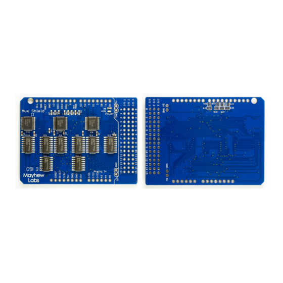
Mux Shield II
User Guide
TI 74HC595
shift
1
Advertisement
Table of Contents

Summary of Contents for Mayhew Labs Mux Shield II
-
Page 1: Table Of Contents
Mux Shield II Mayhew Labs User Guide Table Of Contents: Introduction Hardware Description Pin Descriptions Freeing up Pins by Using Solder Jumpers Suggested I/O Connectors MuxShield Library for Arduino _________________________________________ Introduction Sometimes you need extra inputs and outputs on your Arduino; maybe you’re taking readings from dozens of sensors or controlling a bunch of LEDs. -
Page 2: Pin Descriptions
Mux Shield II Mayhew Labs User Guide Pin Descriptions Name Description Select 0: Acts as address input S0 for multiplexers IC7, IC8, IC11 when OUT MODE is low; acts as serial clock SCLK for shift registers IC3 and IC4 when OUT MODE is high Select 1: Acts as address input S1 for multiplexers IC7, IC8, IC11 when OUT MODE is low;... - Page 3 Mux Shield II Mayhew Labs User Guide To free up Arduino pin 11, and hardwire row I/O2 as either input or output: 1. Cut the trace between the pads of SJ3 (shown in red). A solder jumper can be placed between...
-
Page 4: Suggested I/O Connectors
Mux Shield II Mayhew Labs User Guide Suggested I/O Connectors You can use any standard 0.1” spaced headers with the Mux Shield. The following connectors make life a little easier since they come as 3-row x 16-pin packages in male or female, vertical or right angle. The female connectors work well if you’re using jumper wires;... -
Page 5: Muxshield Library For Arduino
Mux Shield II Mayhew Labs User Guide MuxShield Library for Arduino The MuxShield library is used to make controlling the Mux Shield hardware more straightforward than hardcoding each control signal in every sketch. It wraps up all of the control logic into functions that make your code cleaner. - Page 6 Mux Shield II Mayhew Labs User Guide void digitalWriteMS(int io, int chan, int val) Description: Set the output state of one of the shield’s I/O pins Parameters: - io: 1, 2, or 3 corresponding to which row you want to set...
Need help?
Do you have a question about the Mux Shield II and is the answer not in the manual?
Questions and answers