Table of Contents
Advertisement
Quick Links
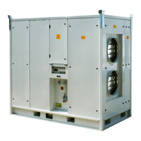
Compact Cool 100 (LU17)
For further documentation see:
http://www.oc-verhulst.nl/
MANUAL
Rental Units v5.1 2021
OC Verhulst
Albert Einsteinweg 10
5151 DL Drunen
The Netherlands
Tel.: +31(0)416 – 672 200
Fax: +31(0)416 – 340 785
www.oc-verhulst.nl
OC Verhulst is a trade name of Verhulst Klimaattechniek
B.V., part of Orange Climate.
Advertisement
Table of Contents

Summary of Contents for OC VERHULST Compact Cool 100
- Page 1 OC Verhulst For further documentation see: Albert Einsteinweg 10 5151 DL Drunen http://www.oc-verhulst.nl/ The Netherlands Tel.: +31(0)416 – 672 200 Fax: +31(0)416 – 340 785 www.oc-verhulst.nl OC Verhulst is a trade name of Verhulst Klimaattechniek B.V., part of Orange Climate.
-
Page 2: Table Of Contents
Contents Contents ................................2 Introduction ..............................5 Warranty ..............................6 Description of the Compact Cool ........................ 7 3.1. Design types ............................7 3.2. Compact Cool system principle ......................7 General maintenance / securing......................... 8 4.1. Maintenance of the Compact Cool ..................... 8 Description of the components ........................ - Page 3 7.4. Dual position switch (start/stop):....................... 17 7.5. Control panel: ........................... 17 7.6. Fans: ..............................17 7.7. Three-way valve: ..........................17 7.8. Defrosting cycle: ..........................18 7.9. tERA Portal: ............................18 7.10. Control Technology error messages: ................... 18 7.10.1. Dirty filter message | not urgent: ....................18 7.10.2.
- Page 4 11.6. Selection of menus ........................31 11.7. Main menu and start-up ........................ 32 11.8. Switching on/Switching off the unit ....................33 11.9. Setpoint ............................34 11.9.1. Setpoint temperature ........................ 34 11.9.2. Setpoint speed .......................... 34 11.9.3. Setpoint voltage ........................34 11.9.4.
-
Page 5: Introduction
OC Verhulst reserves the right to change the construction and/or design of our Compact Cool without prior notice at any time or to modify previously made deliveries accordingly. The Compact Cool comes in four versions: Compact Cool 50, Compact Cool 50E, Compact Cool 100 and Compact Cool 200. -
Page 6: Warranty
The warranty lapses immediately and automatically if: • Service and maintenance are not carried out strictly in accordance with the instructions, repairs are not carried out by OC Verhulst personnel or are carried out without the prior written permission of OC Verhulst. •... -
Page 7: Description Of The Compact Cool
The Compact Cool can be connected with an electric plug. Compact Cool 100 Design types 3.1. The Compact Cool 100 has a nominal output of 100 kW, maximum cooling capacity at 12,500 m /h and is suitable for both indoor and outdoor installation. Compact Cool system principle 3.2. -
Page 8: General Maintenance / Securing
Maintenance must be carried out by authorised and qualified personnel, see chapter 6. For maintenance, you can use the service organisation of OC Verhulst, which offers you a maintenance contract for this. If you notice any defects and/or deviations, please report this to our service organisation immediately. When reporting, it is important to mention the order number of the unit (this number is indicated on the model plate of the unit). -
Page 9: Description Of The Components
Switch panel behind closed door (CE) Can only be opened with special tools The dampers of the Compact Cool 100 are manually operated and can be locked. Electrical connection (16 ampere) Menneke plug, 5-pin without 0. In the following subchapters, all components are listed separately and the required maintenance is indicated. -
Page 10: Defrosting Heater (Water)
! CAUTION: Be careful when changing filters. Chemical, biological or microbiological substances may have collected in the filter. These substances can be hazardous to health. They may also end up as residue at the bottom of the section. Always use personal protective equipment (safety glasses, gloves and P2 dust mask), never throw filters around, pack the dirty filters before moving them (in a box or bag). -
Page 11: Drip Tray Maintenance
5.6.1. Drip tray maintenance Dirt, possibly including substances of a biological or microbiological nature, collects in the drip trays of coolers. These substances may pose a threat to health. Therefore, be careful when cleaning these drip trays. The drip tray under the cooler must be checked for dirt and cleaned if necessary. Droplet eliminator/separator 5.7. -
Page 12: Fan Maintenance
The fans are controlled by the PLC and communicate via ModBus. Because EC motors are used, there is no risk of the fans turning in the wrong direction. Please note that a leakage current is present. ! CAUTION: The main switch of the unit must be switched off and locked at all times when handling or working on the unit! ! CAUTION:... -
Page 13: Control Panel
Control panel maintenance The control panel should only be cleaned periodically on the outside with a non-aggressive cleaning agent. Inspect the panel and if necessary report any damage and have it repaired by OC Verhulst. Version 5.1_2021 (31 March 2021) -
Page 14: Switch Panel
Switch panel 5.12. The switch panel is fully compliant with NEN-EN-60204-1. On delivery of the Compact Cool, the electrical diagram is located in the logbook (inside the service door/hatch). The electrical control is carried out by the control unit housed in the controller compartment. Please refer to the operating instructions of the control system used in your unit (and, if applicable, the electrical diagram) for details on how to operate and reset the various protection devices. -
Page 15: Maintenance Schedule For Operating Personnel + Qualified Personnel
Maintenance schedule for operating personnel + qualified personnel Number of inspections Components to be checked on the Compact Cool per year * Air control dampers Check the dampers for proper functioning and wear Regularly Check the condition of the volume control damper (dirt, seals, actuator) Filters Check the pressure differential across the filters, replace the filters if necessary Check the mounting of the filters (leakage) -
Page 16: Damaged Or Missing Pictograms
The Compact Cool is equipped with the following pictograms as standard: Control panel location Watch out for rotating parts Secure before opening OC Verhulst model plate High Voltage Rotating Parts Missing or damaged pictograms should be (re)affixed as follows. When affixing pictograms, proceed as follows: Clean the surface with a non-aggressive degreaser. -
Page 17: Control Technology
For control technology, please refer to the user manual supplied with the product, which can also be found on our website www.oc-verhulst.nl. In OC Verhulst units that are frequency-controlled or equipped with EC technology, residual current devices, neutral grounding can be used as extra protection, provided that local safety regulations are observed. A grounding fault can cause a direct current in the discharge current. -
Page 18: Defrosting Cycle
Defrosting cycle: 7.8. Defrosting cycle is started manually via a push button. The first time the button is pressed, the defrosting cycle of 10 minutes starts. After each press, 10 minutes are added. The time can be read from the display. Pressing the push button for 5 seconds resets the defrosting cycle and restarts the standard control strategy. -
Page 19: Defrosting Cycle Active
Delivery and transport 8.2. We advise you to check your Compact Cool immediately upon delivery by OC Verhulst for transport damage. Report any transport damage immediately to the carrier and within 24 hours to OC Verhulst. If transport damage is not reported immediately, all warranty claims become null and void. -
Page 20: Horizontal Transport
These should protrude through the frame. The use of chains is not recommended. ! CAUTION: During transport by OC Verhulst, all openings as well as other connections are covered. Leave this sealing intact for as long as possible to prevent dirt and moisture from entering the unit. -
Page 21: Final Placement
Final placement 8.4. When deciding on the location for the Compact Cool, sufficient space around the air handling unit should be taken into account to allow for operation and the work to be carried out. At least 1 metre should be available at the front. The unit must be able to suck in and extract air freely. -
Page 22: Commissioning
Water connection, see photo: Defroster supply water Defroster return water Supply water Return water Commissioning 8.6. The installation of the Compact Cool must comply with the general and locally applicable building, safety and installation regulations of the local authorities and the electricity and water companies. Connect the power supply to the wall socket as shown in the electrical diagram supplied. -
Page 23: Starting
To decommission your Compact Cool, carry out the following actions (see also chapter 8.3). Remove the start command from the control panel (see the electrical diagram). If there is a risk of freezing, OC Verhulst recommends that you drain the water circuit (if present) and blow it dry using compressed air. -
Page 24: Safety
The safety information in these operating instructions has been compiled as a guide for handling the unit safely. OC Verhulst does not guarantee the completeness of this information and can therefore not accept liability for any inaccuracies. -
Page 25: Safety Measures
All live parts are designed to be touch-safe in order to prevent accidents during maintenance work. • It is very important that the protections fitted by OC Verhulst remain in place or that - if removal for maintenance is required - the original protections are refitted in the original manner. A number of parts carrying a safe voltage (<50V) have not been designed to be touch-safe. -
Page 26: Display Instruction
Display instruction The following explains the operation of the COMPACTrs1.0. Graphical operating display 11.1. The control unit contains 6 operating keys and a graphical, LED-lit display. It offers the possibility of an alarm log and four interfaces. Display and operating buttons 11.2. - Page 27 Counter for defrosting activated by push button Current status Fan F01 Current status Fan F02 Current status Fan F03 (not applicable to Compact Cool 100) Current status Fan F04 (not applicable to Compact Cool 100) Current status Belimo Current unit mode: Heating, Cooling, Defrosting Current status of the unit: Off / On / On by task scheduler In the external Quickstart you will find a brief user explanation.
-
Page 28: P&Id Diagram
Belimo 3-way valve TT04 Return water temperature TT05 Supply water temperature TT02 Supply air temperature (internal) TT03 Supply air temperature (external) F01 & F02 Fans 2 pcs (Compact Cool 100) Supply air damper 2x (manually operated) Version 5.1_2021 (31 March 2021) -
Page 29: Io List C.pcoe Mini
EBM Papst fan connection Modbus RTU Master 19200, 8,1, Equal Fan F01 Address 2 Fan F02 Address 3 Fan F03 Address 4 N/A for Compact Cool 100 Fan F04 Address 5 N/A for Compact Cool 100 Version 5.1_2021 (31 March 2021) -
Page 30: User Interface With Display
User interface with display 11.5. The controller is equipped with an interface with display. The user interface consists of an easy-to-read alphanumeric LCD display equipped with LED-lit function keys. The screens shown on the user interface display the data provided by the I/O module of the controller. The controller is operated by means of a 6-button menu structure and provides the operator with an alarm log plus four different menu levels: Information, Operation, Service and Factory. -
Page 31: Selection Of Menus
If there is more than one active alarm message, you can scroll between them using the (Up) (Down) • key. Pressing the (Alarm) button again for at least 3 seconds will manually acknowledge the alarm • messages and clear them from the display unless other messages are active (they will be stored in the logbook). -
Page 32: Main Menu And Start-Up
Main menu and start-up 11.7. After the controller is switched on, the following procedure is shown in one work flow: Initialising and booting up the CPU (wait 15 seconds) After initialisation, the start screen is displayed: Current selected sensor (ext (external) or int (internal)) Current supply temperature Current air inlet (intake) temperature Fan speed setting by analogue input... -
Page 33: Switching On/Switching Off The Unit
Switching on/Switching off the unit 11.8. In this menu, the user can switch on the unit. The corresponding menu screen is as follows: The unit can now be used when the following conditions are met: Either the external On/Off is set or the task scheduler must be activated. -
Page 34: Setpoint
Setpoint 11.9. Setpoint temperature 11.9.1. Set the temperature for controlling the Belimo valve based on the PID controller. The controlling sensor is either the internal or - if connected - the external temperature sensor for the supply air. The setpoint screen is as follows: Note: Depending on the setting in unit configuration (cooling or heating), this setpoint applies to the controller. -
Page 35: Manual Mode
Start time defrosting 1: 08:00 - 08:20 Start time defrosting 2: 12:00 - 12:20 Start time defrosting 3: 13:00 - 13:20 Start time defrosting 4: 23:00 - 23:20 Start time defrosting 5: - (not used at the moment) Start time defrosting 6: - (not used at the moment) Defrost start time 7: - (not used at the moment) Defrost start time 8: - (not used at the moment) Defrosting starts at 8:00 and stops at 8:20. -
Page 36: Information
Information 11.10. Enter this menu to get all current values and data on the fans, the digital and analogue input and output signals and the unit's status. Description Screen standard Current values, readable by analogue input signals Current analogue and digital output signals Current digital input signals Current status and fan data. - Page 37 Current number of operating hours of the unit. Measured time of power outage of the unit - Time - Duration Version 5.1_2021 (31 March 2021)
-
Page 38: Table Of Alarm Messages
Table of alarm messages 11.11. The alarm messages table is as follows: Alarm ID Type Description Manual reset Error in the amount of data written to memory Manual reset Error writing to memory Automatic reset Alarm message from supply temperature probe Automatic reset Alarm message from the supply coil temperature probe Automatic reset... - Page 39 Automatic reset DC voltage high EBM 2 Automatic reset Supply voltage high EBM 2 Automatic reset Line resistance high EBM 2 Automatic reset Offline EBM 3 Manual reset Phase fault EBM 3 Manual reset Motor blocked EBM 3 Manual reset Undervoltage power supply EBM 3 Manual reset Overvoltage power supply EBM 3...
-
Page 40: Other Functions
Other functions 11.12. 11.12.1. Indicator lights connected to digital output Dirty filter indicator light (orange) At Delta-P, the filter must be replaced. When the pressure drop is too high, the contact opens. After a delay of 60 seconds, the orange light on the control panel will come on. When the contact is closed again, the alarm will disappear after 60 seconds. -
Page 41: Belimo
11.13.3. Belimo In the sensor menu, the deactivation can be determined for each sensor. 11.13.4. Configuring the unit In the configuration of the unit, the mode for the unit can be selected. This affects the PI controller for the Belimo valve. Selecting cooling or heating changes the control direction of the PI controller algorithms. In addition, the number of fans can be selected.
Need help?
Do you have a question about the Compact Cool 100 and is the answer not in the manual?
Questions and answers