
Summary of Contents for FLYLINE MoCo
- Page 1 MOCO MODULE (MOTION CONTROL) Manual for MoCo firmware V1.10 Copyright © 2017 PhotoShip One LLC - www.PhotoShipOne.com...
- Page 2 © 2017 PhotoShip One, LLC. All rights reserved. PhotoShip One, LLC Mesa, AZ 85209 www.photoshipone.com flyline@photoshipone.com Except as expressly provided herein, no part of this guide may be reproduced, transmitted, disseminated, downloaded or stored in any storage medium, for any purpose without the express written permission of PhotoShip One.
- Page 3 MANUAL REVISION HISTORY REVISION DATE COMMENTS DOWNLOAD LINK 4/15/2017 Initial Release 05/23/2017 • Firmware version 1.1 changes • Added Manual Revision History & Firmware Changelog • Added DX6 switch location graphic • Revised Ping-Pong Mode Operation • Added AR8000 rx setup information FIRMWARE CHANGELOG VERSION DATE...
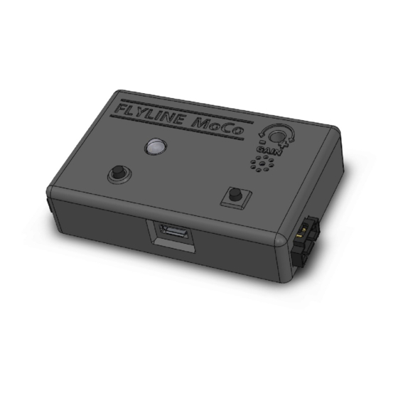
- Page 4 The MoCo Module allows the FlyLine trolley to ‘know’ its position on the rope. This is useful for automatic control of the system. The user can set endpoints at each end of the rope that the trolley will not cross when properly configured.
-
Page 5: Table Of Contents
TABLE OF CONTENTS 1. INSTALLATION 1.1 Mount Sensor Disc to Outrigger Wheel 1.2 Mount Sensor to FlyLine Frame 1.3 Mount MoCo Module to FlyLine Frame 1.4 Connect RC Control Cables 1.5 Connect & Route Sensor Cable 2. MOTOR CONTROLLER SETUP 2.1 DIP Switch Assignments... -
Page 6: Installation
1. MOCO MODULE INSTALLATION 1.1 Mount Sensor Disc to Front Outrigger Wheel If looking at the FlyLine trolley with the motor controller and end of the motor facing you, the front of the trolley is to your right. Front Attach the sensor disc to the outrigger wheel. -
Page 7: Mount Moco Module To Flyline Frame
1.5 Connect & Route Sensor Cable Connect the wheel sensor cable to the connector on the right side of the MoCo unit. Route the cable along the trolley frame and secure with cable ties. The cable will need to route from the outside of the frame to inside of the frame at the sensor. -
Page 8: Motor Controller Setup
Red wire connects to 5V White wire connects to S1 Connect the plug end of the data cable to Position 5 on the MoCo unit with the WHITE signal wire on the top position, BLACK at the bottom. Copyright © 2017 PhotoShip One LLC -... - Page 9 2. MOTOR CONTROLLER SETUP 2.4 - Connections Diagram for Spektrum AR610 When all connections are made the system should be as follows: Verify RC controls and data cables are oriented correctly with WHITE, RED, BLACK wires in proper position. Copyright © 2017 PhotoShip One LLC - www.PhotoShipOne.com...
- Page 10 2. MOTOR CONTROLLER SETUP 2.5 - Connections Diagram for Spektrum AR8000/AR8010T When all connections are made the system should be as follows: Verify RC controls and data cables are oriented correctly with WHITE, RED, BLACK wires in proper position. Copyright © 2017 PhotoShip One LLC - www.PhotoShipOne.com...
-
Page 11: Motor Wire Connections
2. MOTOR CONTROLLER SETUP 2.6 - Motor Wire Connections Diagram You may NOT ignore this page if you have ordered the MoCo module separately from a FlyLine and you are installing it yourself. You MAY ignore this page if you have received a prebuilt FlyLine system from PhotoShip One with the MoCo already installed as we have already completed this verification. ... -
Page 12: Spektrum Controller Setup
Spektrum DX6, DX7S, DX8 (silver & black), and DX9 here: http://www.photoshipone.com/documentation/Spektrum_MoCo.zip Other RC systems (Futaba, JR, etc) have not been tested and may not work properly with the MoCo module. If you purchased your FLyLine system from us with the Motion Control module installed, disregard this Section. - Page 13 3. SPEKTRUM CONTROLLER SETUP 3.4 - Switch Assign Aux 1 Channel to Button We recommend the Aux 1 channel (used for setting end points) be assigned to the ‘Bind’ button on the Spektrum controller. On the DX 6 this button is defined as button ‘I’. Go to System Menu >...
-
Page 14: Mode Selection
For information on setting end points and operating in End Point Mode, please refer to section 5.2. To exit Ping-Pong mode push and hold the left ‘Circle’ button on the MoCo Module or AUX button on Spektrum for 2 seconds. The LED indicator will illuminate... - Page 15 For information on conducting sensor test please refer to section 5.4 To exit Sensor Test mode simultaneously push and hold the left ‘Circle’ button and the right ‘Square’ button on the MoCo Module for 2 seconds. The LED indicator will illuminate GREEN and you will hear one tone from the beeper letting you know you are in Manual Control/Auto End Point Mode.
-
Page 16: Operation
Manual Control/Auto End Point Mode AUX 1 GEAR (AR610) AUX 2 (AR8000) ON (1) The MoCo Module is in full manual control when the ‘Gear’ OFF (0) switch on the Spektrum controller is in the ‘Off’ position. The LED indicator will be solid GREEN. -
Page 17: Gain Calibration
To know which number value the Gain is currently set to, simply push the right Square button on the MoCo module for 1/2 second then release. You will hear a series of tones from the beeper that denote what value the gain is set. 1 beep = Gain Value 1, 2 beeps = Gain Value 2, 3 beeps = Gain value 3, and so on to 10. - Page 18 2. Verify the Gain value is set to 10 by pressing and releasing the right ‘Square’ button on the MoCo module and listening for the number of tones from the beeper. There will be 10 tones if the Gain value is set to 10.
-
Page 19: Ping-Pong Mode
4. Rotate the outrigger wheel one revolution and count the number of beeps you hear. You should hear 24 beeps with one full revolution. Sensor test mode should be done each time the FlyLine is rigged on a rope to verify the sensor, sensor disc, and sensor cable are properly functioning. - Page 20 Aux1- OFF Thro - LOW With these settings stored in Fail Safe of the Spektrum, a loss of signal would force the MoCo unit into Auto End Point or Ping-Pong mode with motor power set to off or very slow.
- Page 21 We hope you enjoy the FlyLine. If you have further questions please contact us at flyline@photoshipone.com or visit our contact page of our website at http://photoshipone.com/ contact-us/ Copyright © 2012 PhotoShip One LLC - www.PhotoShipOne.com...
Need help?
Do you have a question about the MoCo and is the answer not in the manual?
Questions and answers