Table of Contents
Advertisement
Quick Links
Advertisement
Table of Contents

Summary of Contents for MANIKK ADSR
- Page 1 MANIKK ADSR Advanced Envelope Generator - Eurorack Module Users Guide...
- Page 2 M A N I K K A D S R Users Guide Document version 1.03 ã 2019 manikk SWEDEN...
-
Page 3: Table Of Contents
T able of Contents Front panel layout ..............1 Welcome ..................2 Overview ..................3 User interface and navigation ............ 4 Feature-buttons ................4 MOD-button ................4 MOD-mode ..................4 Config-mode ..................4 LED’s ..................5 Normal run mode ................5 MOD mode .................. - Page 4 Gate input jack ................. 13 EG output jack ................. 13 Otto Active Expander pins ............14 Pins on the back of the ADSR module .......... 14 Active Expander output jacks ............16 MIDI pins .................. 17 MIDI Implementation ..............18 Technical details ..............
-
Page 5: Front Panel Layout
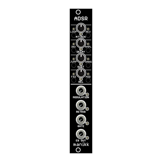
M A N I K K A D S R Front panel layout... -
Page 6: Welcome
Welcome Congratulations to your purchase of this module. The manikk ADSR is an advanced envelope generator, capable of producing normal ADSR-envelopes but also a number of experimental envelopes. In loop-mode, it can also be used as LFO. It is a linear envelope generator with modulation capability. -
Page 7: Overview
Overview Manikk ADSR is a linear envelope generator. You can use it to create normal linear ADSR-style envelopes, but you can also use the parameters and modulation capabilities to create other type of envelopes. In loop-mode the module can be used as LFO. By using the jump-parameter, the module can be used as a gate delay. -
Page 8: User Interface And Navigation
User interface and navigation Feature-buttons All buttons except for MOD controls different features directly. When you make a short press on those buttons, you turn that feature on or off. A red led indicates if the feature is on. MOD-button The MOD-button is special. -
Page 9: Led's
LED’s The module can be in three different modes described here: Normal run mode The leds indicates the status of the 7 features. Use the buttons to turn on or off. MOD-led is turned off. Modulation led shows if the modulation input signal peaks. The modulation range is -5V to +5V. -
Page 10: Parameters On The Front-Panel
Puts the envelope generator in looping mode. As long as the gate is high, it will create a looping ADSR curve. In loop-mode the module acts like a LFO. There is a config-parameter that where you can select the sustain-mode. The sustain- mode controls how the sustain state should behave. -
Page 11: Rev
Modulating this parameter turns the feature on or off. Reverse the order of the phases and run “backwards”. Normally the order of the phases is ADSR. When reversed, the order is RSDA. In reverse mode, it starts with Release and goes to Sustain, stays at the sustain until the gate goes low, then it finishes with a Decay and finally Attack back to zero. - Page 12 In config-mode you use the MOD-button to cycle to the next config parameter and you use the LOOP-button to cycle the values for the currently selected config- parameter. The value for the currently selected config-parameter is indicated by the four A, D, S, R-leds.
-
Page 13: Config Parameters
Config parameters See the chapter “User interface and navigation” how to enter config-mode. Use short press on MOD-button to step to the next config-parameter. Use short press on LOOP-button to change the value for the currently selected parameter. The config parameters are cycled in the following order: Alternative modulation style MOD and MODULATION leds are blinking. -
Page 14: Retrig-Type
Retrig-type How the retrig should behave: 1) Retrig always restarts from zero with full Attack-time (or Release-time when reversed). 2) Retrig restarts from the current level (usually not zero) with full Attack-time (or Release-time when reversed). 3) Retrig restarts from the current level and with a calculated shortened time that depends on the current level. -
Page 15: Range-Mode
2) Divided by 2 3) Divided by 4 4) Divided by 8 Range-mode The time-range of the module can be adjusted in 4 steps: 1) Normal range, each time-potentiometer has a max of about 2 seconds. 2) Times multiplied by 2 3) Times multiplied by 4 4) Times multiplied by 8 MIDI-mode... -
Page 16: Learn-Mode
Learn-mode When you have selected the correct baud-rate and have hooked up a midi-keyboard that sends MIDI to this module, you can press a key on the MIDI-keyboard. The module will then detect the MIDI channel, store that and then leave config-mode and go back to run-mode. -
Page 17: Connections
Connections Power connector Located at the bottom on the backside. Here you connect the normal Eurorack power connector (included). Two rows with: +12V, GND, GND, GND, -12V. Make sure you orientate the connector the correct way. The negative -12V is marked on the pcb with the text “red strip”. -
Page 18: Otto Active Expander Pins
The expander gives 8 additional digital outputs. Pins on the back of the ADSR module These 6 pins are located on the lower right side of the ADSR backside. Between the power connector and the microprocessor board. Pin (top to bottom) - Page 19 How to connect an active expander to the ADSR module.
-
Page 20: Active Expander Output Jacks
Active Expander output jacks High=+5V, Low=0V Jack (top to bottom) Function High in Attack phase High in Decay phase High in Sustain phase High in Release phase High when modulation input peaks -5V or +5V High when in freeze mode High when idle (no ongoing envelope) High during an ongoing envelope... -
Page 21: Midi Pins
TX (top pin on the backside) +5V (bottom pin, near the top of the microprocessor board) The RX and GND pins should be connected to the MIDI output pins of the manikk MIDI THRU module or the manikk Otto MIDI module. -
Page 22: Midi Implementation
MIDI Implementation The module can receive and act upon a number of control change messages received on the base channel. The base-channel is selected with the midi-learn function in the MIDI-mode config parameter (see config-parameters). All CC’s respond to a value 0-127 and will be scaled up or down depending on the parameter range. - Page 23 0-127, will be divided by 32 and sets 1 of the Cfg-Ampl 4 possible settings for amplitude. 0-127, will be divided by 32 and sets 1 of the Cfg-Rang 4 possible settings for range. Cfg-Gate 0-127, will be divided by 32 and sets 1 of the 3 possible settings for gate-type.
-
Page 24: Technical Details
Very important that you attach your return- address to the device, so we know where to return the repaired device. 4) Manikk will repair or replace the device if the problem is covered by the warranty. We will send the repaired device back to you.
Need help?
Do you have a question about the ADSR and is the answer not in the manual?
Questions and answers