
Summary of Contents for DOCTOR SMILE WISER 3
- Page 1 WISER 3 DIODE LASER L A 12D 001.X USER MANUAL DIODE LASER LA12D001.X - USER MANUAL LI12D001.1_EN 2021-01-12...
- Page 2 INDEX INTRODUCTION 1.1. VERSIONS LIST 1.2. INTENDED USE 1.3. SYMBOLS USED 1.4. APPLIED PART SAFETY 2.1. ESSENTIAL REQUIREMENTS 2.2. GENERAL SAFETY DISPOSITIONS 2.3. WORKING AREA 2.4. INDIVIDUAL SAFETY MEASURES 2.5. OCULAR RISK CERTIFICATIONS 3.1. CE DECLARATION OF CONFORMITY 3.2. CE CONFORMITY MARKING 3.3.
- Page 3 INTRODUCTION Diode laser LA12D001.x (commercially identified as WISER 3) is a medical device that uses a laser source. This user manual is issued with reference to all products listed at the following chapter which differ each other in wavelength and power emission according to the table below. If not specified otherwise, the generic code LA12D001.x refers to all devices.
-
Page 4: Intended Use
1.2. INTENDED USE This laser equipment named “DIODE LASER” is a medical device and its application fields are: • DENTAL SURGERY • DENTISTRY • DENTAL THERAPY Examples of use 1.2.1. Some application fields are orthodontics, endodontics, periodontology, herpes therapy, canker sores, chelitis, conservatives, whitening, care and maintenance of implants-peri-implantitis. -
Page 5: Symbols Used
In case of whitening activity, use in the presence of infections, gingival lesions or carious diseases on the dental elements must be avoided. ATTENTION The improper use of this laser device might lead to unwanted, sometimes dangerous effects. 1.3. SYMBOLS USED Symbol “Attention”... - Page 6 SAFETY DANGER The device must be installed in environments with electrical systems compliant with the regulations in force in your country. DANGER Do not allow the use of the device to non-professional operators or who have not read the instruction manual. Always check the device is in good condition.
-
Page 7: Essential Requirements
ESSENTIAL REQUIREMENTS 2.1. The device within its casing and in the test conditions described maintains operation and emission stability within the standard tolerance of ± 20%. GENERAL SAFETY DISPOSITIONS 2.2. During its normal use, the laser device laser exposes the human body to laser light radiation; therefore it is important to scrupulously read and follow all the safety dispositions listed in this chapter. - Page 8 It is possible to connect the interlock with a remote switch as shown in the picture below. INDIVIDUAL SAFETY MEASURES 2.4. All the safety measures here described must be scrupulously followed in order to avoid accidental exposure to laser radiation. •...
- Page 9 OCULAR RISK 2.5. Eyes can be seriously damaged in case of unprotected exposure to laser light. For this reason it is compulsory to wear protection glasses both for the operator and for the people present in the work area. Use only glasses with the same specifications as those supplied. In case of breakages or other necessities, it is advisable to contact the supplier to request the same or similar glasses with the same characteristics as those supplied.
- Page 10 Model LA12D001.4 LA12D001.5 Wavelength Laser Diode Diode Emission Continue/Pulsed Continue/Pulsed Power Divergence 220 mrad 220 mrad Diameter 0.2mm 0.2mm Exposure time Observation Direct Light Direct Light (at 0.1 m) DNRO 2,510 3.,590 Model LA12D001.6 LA12D001.7 LA12D001.8 Wavelength Laser Diode Diode Diode Emission Continue/Pulsed...
-
Page 11: Ce Declaration Of Conformity
CERTIFICATIONS CE DECLARATION OF CONFORMITY 3.1. For MEDICAL LASER device named L A 12D 001.x S/n: ____ Manufactured by LAMBDA SpA Under Annex II of directive 93/42/CEE, except point 4, transposed from DL 46/97 and its integration with standard 2007/47/CE issued with Law Decree 37 of 25/01/2010 and with the application of standard 99/05/CE. -
Page 12: Ce Conformity Marking
CE CONFORMITY MARKING 3.2. This product is marked with the CE label according to the European standard applicable for medical devices: CEE 93/42. The manufacturer of this product is: LAMBDA SpA via dell'Impresa 1 36040 Brendola (VI)- Italy +39 0444 349165 info@lambdaspa.com NAMEPLATE 3.3. - Page 13 3.4. WARNINGS The device works discontinuously as per data reported in the nameplate and at the chapter “TECHNICAL SPECIFICATIONS”. The manufacturer is not responsible for the direct and indirect effects due to the use of the device. These effects remain under the direct responsibility of the medical personnel performing the treatments.
-
Page 14: Installation
INSTALLATION CHECK ON DELIVERY 4.1. Upon arrival of the goods and in the presence of the carrier, it is important to pay accurate attention that the shipped material is correct and intact. In particular: • The number of parcels and corresponding codes. •... -
Page 15: Electric Requirements
ELECTRIC REQUIREMENTS 4.4. It is important to verify that the power cable is not damaged before using the laser system. In particular, the cable plug must be compatible with the powering network socket. Do not use adapters, extensions or multiple sockets of any type. The power supply complies with the CEI EN 60601-1 standard and has the following features:: Model SINPRO MPU101-106... -
Page 16: Operation Mode
OPERATION MODE 5.1. OVERVIEW DISPLAY / TOUCH SCREEN EMERGENCY STOP USB INPUT ON/OFF SWITCH HANDPIECE HOLDER CABLE PEDAL INPUT FIBER INPUT POWER SUPPLY INPUT BATTERY INTERLOCK DIODE LASER LA12D001.X - USER MANUAL LI12D001.1_EN 2021-01-12... -
Page 17: Accessories Included
ACCESSORIES INCLUDED INCLUDES: FIBER/HANDPIECE INTERLOCK SWAB OPTICAL FIBER BOX 5 BOXES 01 tip ENDO (Blue - box 04) 01 tip PERIO (Yellow - box 04) 01 tip SURGERY ( Green - box 04) 01 tip IMPLANT (White - box 04) 01 tip THERA (Black - box 04) PIEGA TIP (30°... - Page 18 5.3. LASER DEVICE PREPARATION 1. Insert the fiber holder (A) into the 2. Remove the protective cap of the diode dedicated hole. output. 4. Insert and screw the fiber (A), connect interlock (B) and power supply (C). 3. Remove the protective cap of the fiber D connector is for the cable of the pedal 5.
-
Page 19: Pedal Installation
PEDAL INSTALLATION 5.4. The Bluetooth pedal is powered by N.3 non-rechargeable 1.5V AA batteries. Make sure that they are present in the battery compartment before proceeding. Turn on the pedal using the switch on the bottom. The flashing red LED indicates that batteries are running low. Replace the batteries. The green LED is on when the pedal is pressed. - Page 20 5.5. HANDPIECE AND TIP INSTALLATION On delivery of the device the tips supplied in the packaging have not been sterilised Different tip sizes are available for different applications. They are colour-coded for easy identification. The tips include a screw on ring. APPLICATION COLOUR CODE Size...
- Page 21 TIP BENDING Use only the accessory provided to bend the tip as required. 1. Insert the tip in the hole of the tip shaper 2. Bend the tip to obtain the desired shape by pressing the metal part. 1. Insert the tip in the hole of the tip shaper 2.
- Page 22 WHITENING AND STIMULATION ACCESSORIES INSTALLATION WHITENING TIP (LARGE AREA ARCH) For whitening procedures, screw the large area whitening accessory to the handpiece, after removing the protection cap. BIOSTIMULATION TIP For intraoral biostimulation procedures screw the appropriate tip on the handpiece. FLAT TOP (optional) For extra-oral biostimulation procedures, insert the connector of the Flat Top in the Wiser handpiece tip.
-
Page 23: Cleaning And Sterilization
CLEANING AND STERILIZATION ATTENTION Every component which can enter in contact with the patient must be sterilized. Separate all the elements and clean them carefully before sterilizing, by removing any trace of organic residual. 6.1. HANDPIECE MAINTENANCE the handpiece is made up of two separable parts: the main laser body attached to the fibre and an autoclavable screw on cylinder. - Page 24 6.2. CLEANING AND STERILIZATION It is suggested to always clean and disinfect handpiece and tip before sterilization to remove any trace of organic residual. CLEANING AND DISINFECTION 1. Soak a piece of gauze in 2. Wrap the tip in the gauze and let 3.
-
Page 25: System Operation
SYSTEM OPERATION DANGER Before the use of laser, ensure that all safety measures described in this manual have been put into place. DANGER All users (doctors and patients) have to use protective goggles. DANGER Each deviation/modification from what here described can cause an exposure to dangerous levels of irradiation. - Page 26 OFF-LINE ACTIVATION If Wi-Fi connection is not available, it is possible to follow the off-line procedure by pressing the relative button (on bottom right of the screen). It is required a QR code scanner to proceed (the scanner can be downloaded with a free application).
-
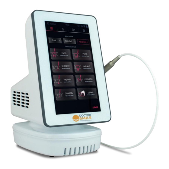
Page 27: Treatment Selection
DEVICE SWITCH-ON 7.2. Turn on the laser using the main switch on the rear of the machine Press the display to accede.to Insert the default password 1- Home page: treatment list: the psw screen. 1-1-1-1 Note: the starting message Note: the password can be can be different from the modified at any time from the shown one. - Page 28 ASSISTED MODE (LAP) The laser device guides the user splitting the treatment in single phases with pre-set values of power and timer. These values cannot be modified and each phase changes automatically. Once the timer ends, the procedure will move automatically to the following step updating parameters and instructions.
- Page 29 ADVANCE MODE (ADV) TIMER POWER 450-808 POWER Each protocol is defined with pre-set parameters (power, pulse type, timer) which can be manually modified. Power and pulse can be modified not individually for each single diode but as average value between the two channels (in a proportional way with preset ratio). 1.
- Page 30 EFFECTS MODE (UBE) The effects mode has N.5 main category, with different preset treatments (effects) : soft, medium, hard, very hard, boost. La lista dei trattamenti utilizzabili è: • ABLATIVE • THERMAL • DECONTAMINANT • BIOSTIMULATING TIMER POWER 450-808 PULSE POWER Each protocol is defined with pre-set parameters (power, pulse type, timer) which can be manually modified.
-
Page 31: Laser Activation
LASER ACTIVATION 7.4. STANDBY Press the button to activate mode READY. READY The device is now ready for the use. OPERATE OPERATE Press the pedal to enable mode and generate laser emission. The yellow signs starts to blink to highlight the laser emission. Release the footswitch or touch any point of the display to stop laser STANDBY emission and return in... -
Page 32: Setting Menu
SETTING MENU 7.7. Select the Setting menu icon to enter in the setting menu: Practice Name / Hours: Language Pointer: Set the intensity of the aiming beam (%) Sound: set the intensity of the audio (3 levels) Brightness: Set the display contrast Use interlock: enable/disable the external interlock system Change password... - Page 33 FAVOURITSE AND PATIENT LIST 7.9. From main screen it is possible to have access to the following functionalities: • Create a list of favorite treatments • Create a list of patients and relative agenda • Verify the counters and the time of use of the device DIODE LASER LA12D001.X - USER MANUAL LI12D001.1_EN 2021-01-12...
-
Page 34: Switching Off
SWITCHING OFF 7.10. Press the main switch on the back of the laser to switch off the device. DO NOT LEAVE THE DEVICE SWITCHED ON WHEN NOT USED WIRELESS MODE / BATTERY RECHARGE 7.11. The device can be used without external power supply thanks to an internal power system made of a lithium battery (“INTERNALLY POWERED”). -
Page 35: External Connection
To remove the battery, unscrew the N.2 lower cross screws and remove the battery cover. Unplug the battery connector. Take the new battery and plug it (the connector is designed so that it is not possible to invert the polarity). Place the battery inside the battery cover and fix it using the N.2 cross screws. -
Page 36: Periodical Maintenance
MAINTENANCE ATTENTION The aiming beam pass through the same delivery system (optical fiber) of the laser beam, so it is strongly suggested to verify periodically the integrity of the fiber, included handpiece and tip If the aiming beam is not visible or its intensity is reduced, this could be a possible sign of failure (handpiece, fiber or laser source). - Page 37 The equipment does not require particular cleaning operation but it is advisable that the following general rules be followed: a. Keep the working area clean by using vacuum cleaners to remove dirt and dust. b. Handpiece and tip must be cleaned as described at the related chapter. c.
-
Page 38: System Errors
SYSTEM ERRORS A pop-up message will appear whenever a system error occurs. ERROR DESCRIPTION Interlock If an external interlock network is not present, verify the interlock check is disabled. If an external interlock network is present verify that the event is under control (for example, the opening of a door) or check that the connections are correct Footswitch... -
Page 39: Spare Parts
SPARE PARTS Product Code Product code DOCTOR SMILE LA12D001.x HANDPIECE LAFIO022.2 WISER 3 LASER (for LA12D001.1) LAFIO022.3 (for LA12D001.5) HANDPIECE COVER LOMAN042.1-A/NC SAFETY GOGGLES LOEYW002.0 (for LA12D001.1) LOEYW022.0 (for LA12D001.5) BIOSTIMULATION TIP COFIL0057-L/NC LARGA AREA WHITENING LAACS099.3 HANDPIECE LENS LAACS072.25 BENDING TIP TOOL LAACS056.2... - Page 40 LAACS008.1 METALLIC SUITCASE MMCAS069.0 Product Code Product code TIP SURGERY LATSU302.4 DOCTOR SMILE LWS – LPLWS004.1 WHITENING KIT Box 4 pcs – green TIP IMPLANTS LATIM302.4 Box 4 pcs –white TIP THERAPY LATHE402.4 - 1 syringe LWS whitening gel 5 g (35% H2O2) Box 4 pcs –...
-
Page 41: Specifications
SPECIFICATIONS LAMBDA SpA Manufacturer Via dell’Impresa - 36040 Brendola (VI) - Italy LA 12D 001.1 (635-808-976 nm) LA 12D 001.2 (635-808-915 nm) LA 12D 001.3 (450-808-976 nm) LA 12D 001.4 (635-450-976 nm) Models LA 12D 001.5 (635-450-808 nm) LA 12D 001.6 (976 nm) LA 12D 001.7 (808 nm) LA 12D 001.8 (450 nm) Power supply input voltage... - Page 42 Pulse duration sensitivity ± 5% Pulse duration (Ton) Adjustable 20 µs - CW Pulse intervals (Toff) Adjustable 20 µs - 999 ms Emission duration Continuous or by timer Adjustment of duration of emission adjustable OFF ÷ 300 sec Timer sensitivity variable Wireless pedal Footswitch...
-
Page 43: Safety Labels
SAFETY LABELS On the laser there are safety labels that include danger notes for the operator and information about the laser device's characteristics. These labels must always be kept in good conditions and should be replaced if they are damaged. Use mild products when you clean the laser. - Page 44 ET-1 ET-3 ET-4 ET-2 ET-5 ET-6 STORAGE CONDITIONS TEMPERATURE: 5 – 50 °C HUMIDITY: 30 – 75 % ATM. PRESSURE: : 700-1060 hPa ET-7 ET-8 DIODE LASER LA12D001.X - USER MANUAL LI12D001.1_EN 2021-01-12...
- Page 45 EMC REGULATIONS (ELECTROMAGNETIC COMPATIBILITY) The existence of regulations for the electromagnetic compatibility is essential to ensure the safety of the appliances and systems, in that there are electromagnetic phenomena with various levels of intensity present in the area where these appliances are normally used. This means that to ensure the electromagnetic compatibility, the device must function correctly within its foreseen working environment.
- Page 46 Guidance and manufacturer's declaration – electromagnetic emissions The device is intended for use in the electromagnetic environment specified below. The customer or the user should assure that it is used in such an environment. Emission test Compliance Electromagnetic environment - guidance The device uses RF energy only for its internal function.
- Page 47 Guidance and manufacturer's declaration – electromagnetic immunity – recommended separation distance The device is intended for use in the electromagnetic environment specified below. The customer or the user of the device should assure that it is used in such an environment. IEC 60601 Compliance Immunity test...
- Page 48 Recommended separation distances between portable and mobile RF communications equipment and the laser device The device is intended for use in an electromagnetic environment in which radiated RF disturbances are controlled. The customer or the user can help to prevent electromagnetic interference by maintaining a minimum distance between portable and mobile RF communications equipment (transmitters) and the laser device as recommended below, according to the maximum output power of the communication equipment.
-
Page 49: Device Disposal
13.1. ESD (ELECTROSTATIC DISCHARGE) WARNING: pin connectors identified with the ESD warning label must not be touched or connected unless all safety indications are implemented. Only technicians authorized properly trained on ESD risks may perform operations on such places. Technicians must firstly verify that the power supply is properly grounded and free from defects. The device is provided with USB connection only for trained personnel who use safety tool against the risk of electrostatic discharge. -
Page 50: Warranty
WARRANTY The manufacturer guarantees its clients that the products are free of defects and are guaranteed for two years. This warranty is not valid for any defect, fault or damage caused by improper use or inadequate maintenance and care. The manufacturer is not obliged to provide assistance under warranty to repair damage caused by other personnel not authorised by the manufacturer.
Need help?
Do you have a question about the WISER 3 and is the answer not in the manual?
Questions and answers