Sign In
Upload
Download
Table of Contents
Contents
Add to my manuals
Delete from my manuals
Share
URL of this page:
HTML Link:
Bookmark this page
Add
Manual will be automatically added to "My Manuals"
Print this page
×
Bookmark added
×
Added to my manuals
Manuals
Brands
VITALI Manuals
Medical Equipment
T5
Technical manual
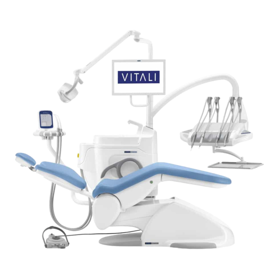
VITALI T5 Technical Manual
Dental unit/chair
Hide thumbs
1
2
Table Of Contents
3
4
5
6
7
8
9
10
11
12
13
14
15
16
17
18
19
20
21
22
23
24
25
26
27
28
29
30
31
32
33
34
35
36
37
38
39
40
41
42
43
44
45
46
47
48
49
50
51
52
53
54
55
56
57
58
59
60
61
62
63
64
65
66
67
68
69
70
71
72
73
74
75
76
77
78
79
80
81
82
83
84
85
86
87
88
page
of
88
Go
/
88
Contents
Table of Contents
Bookmarks
Table of Contents
Table of Contents
Manufacturer's Notes on Installation
Warranty
Circumstances Not Covered by Warranty
Symbols Used
Technical Specifications
Flares Chair Connection Template
Overall Dimensions
Installation Instructions
Assembling the Backrest
Assembling the Backrest Housing
Mounting the Dental Unit Bracket on the Chair
Assembling the Water Unit
Assembling the Instrument Table Arm
Assembling the Tray Table
Grounding Connection for Water Unit - Dental Unit Bracket - Instrument Table Arm
Water Unit Electrical Connection
Assembling the Instrument Table
Hydraulic and Pneumatic Connections for the Instrument Table
Electrical Connections for the Instrument Table
Bowl Suction and Flushing Connection
Hydraulic Connection for Water Unit
Hydraulic and Pneumatic Connections to the Connector Block
Assembling the (Optional) Suction Tube Support Arm and Grounding Connection
Setting the FLARES Chair Movement Dip-Switches
Installation Inspection
Serial Number Location
Accessing the Internal Parts - Flares
Removing the Derivative Housing
Removing Seat Upholstery
Installing Seat Upholstery
Removing the Coplanar Headrest Upholstery
Removing the Double-Jointed Headrest Upholstery
Removing the Backrest Upholstery
Removing the Seat Housing
Disassembling the Headrest Bracket
Removing the Fixed Armrest
Removing the Tilting Armrest (Optional)
Removing the Lower Parallelogram Housing
Removing the Upper Parallelogram Housing
Flares Electrical Unit
Replacing Fuses
Accessing Internal Parts of the Water Unit
Available Versions of the Water Unit
Pressurized Bottle Kit
Operating Diagram of the Pressurized Bottle
Dental Unit Electrical Group
Setting the Dental Unit Card Dip-Switches
Replacing the Dental Unit Card Fuses
Accessing the Internal Parts of the Instrument Table
Instrument Selection Card
Electronic Card Fuses
Accessing the Internal Parts of the Assistant Console
Electrical Connections for the Assistant Console
Hydropneumatic Adjustments
Adjusting and Setting the Table Instruments
Hydropneumatic Diagram
Keypad Functions
Assistant Console
Assistant/Patient Keypad Functions (Located on Console)
Vitali Foot Controls
Electronic Foot Control
Electronic Foot Control Setting and Configuration
Two-Lever Foot Control
Safety Devices
Special Maintenance
Replacing the Vertical Chair Movement Gearmotor
Replacing the Backrest Actuator
Adjusting the Backrest Movement Cradle Friction
Adjusting the Backrest Movement Mechanical Memory
Adjusting the Vertical Chair Movement Mechanical Memory
Adjusting the Instrument Table Support Panel Friction
Assembling the Table Instrument Cords
Replacing the Bowl
Assembling the Instrument Table Arm Stop
Assembling the Instrument Table Arm
Maintenance
Disinfecting
Autoclavable Parts
Periodic Checks
Turbine Lubrication Oil Recovery Device
Checking the Backrest Protection Brush
Checking the Pull Spools
Checking for Wear on the Gearmotor Winding Block
Replacement of the Cannula Terminals and External Suction Hoses
Checking the Internal Suction Hoses
Replacing the Water Unit Filters
Replacing the Air Unit Filter
Requesting Spare Parts and Materials
Wiring Diagrams
Advertisement
Quick Links
1
Table of Contents
2
Wiring Diagrams
Download this manual
T 5 R e - R m
Technician
EN
Table of
Contents
Previous
Page
Next
Page
1
2
3
4
5
Advertisement
Table of Contents
Need help?
Do you have a question about the T5 and is the answer not in the manual?
Ask a question
Questions and answers
Related Manuals for VITALI T5
Medical Equipment VITALI T5 Evo Technical Manual
Dental unit (53 pages)
Medical Equipment VITALI FLARES Technical Manual
Dental unit/chair (88 pages)
This manual is also suitable for:
Flares
Table of Contents
Save PDF
Print
Rename the bookmark
Delete bookmark?
Delete from my manuals?
Login
Sign In
OR
Sign in with Facebook
Sign in with Google
Upload manual
Upload from disk
Upload from URL


Need help?
Do you have a question about the T5 and is the answer not in the manual?
Questions and answers