
Summary of Contents for HIGHLY LIQUID MD24
- Page 1 Highly Liquid MD24 Hardware Revision G MD24 Hardware Revision G User Manual Updated 2011-04-28 Additional documentation available at: http://highlyliquid.com/support/ © 2011 Sonarcana LLC Page 1 / 10...
-
Page 2: Table Of Contents
8.1 Electrical Specifications.......................9 8.2 Logic Wiring........................9 8.3 Servo Wiring........................10 1.0 Important Safety Information To prevent damage to the MD24 and connected devices, and to prevent personal injury: Take reasonable static-control precautions when handling the MD24. This product includes ESD- ● sensitive parts. -
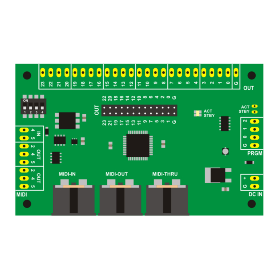
Page 3: Mechanical Drawing
Highly Liquid MD24 Hardware Revision G 3.0 Mechanical Drawing © 2011 Sonarcana LLC Page 3 / 10... -
Page 4: Power Supply
Highly Liquid MD24 Hardware Revision G 4.0 Power Supply To operate, the MD24 must be connected to a battery or other DC power supply. A “wall adapter” supply with appropriate specifications may be used. Power supply requirements: Minimum output voltage: 6VDC ●... -
Page 5: Midi Wiring
Use the MIDI IN and MIDI THRU ports as shown in Figure 5.1. The MIDI THRU port sends an unprocessed replica of the signal received at the MIDI IN port. The MIDI OUT port can be used to retrieve the MD24 configuration via MIDI SysEx message. See MD24 Firmware User Manual. - Page 6 Highly Liquid MD24 Hardware Revision G Figure 5.2: Remote MIDI Connector Wiring © 2011 Sonarcana LLC Page 6 / 10...
- Page 7 Highly Liquid MD24 Hardware Revision G Figure 5.3: On-Board vs. Remote MIDI Connectors © 2011 Sonarcana LLC Page 7 / 10...
-
Page 8: Program Switches
User-supplied “program” switches can be attached as shown in Figure 6.1. If supported by firmware, a program switch can activate “learn mode” and other programming features of the MD24. Use normally-open momentary switches. See MD24 Firmware User Manual for additional details. -
Page 9: Outputs
LEDs, or can trigger other devices requiring a 5V signal. Figure 8.1 shows a circuit which uses an LED to indicate the state of each MD24 logic mode output. The value for current-limiting resistors will depend on choice of LED (1.0kΩ is typical). -
Page 10: Servo Wiring
Exact colors vary by servo brand and model. MD24-to-servo wiring is shown in Figure 8.2. Output #18 is used as an example, but the circuit can be connected to any servo mode output. Repeat as needed for each servo/MD24 output pair.
Need help?
Do you have a question about the MD24 and is the answer not in the manual?
Questions and answers