Table of Contents
Advertisement
Quick Links
HIGH SPEED CIRCULAR SAWING MACHINE
OPERATIONAL
M A N U A L
Thank
you
Dong Jin's High Speed Circular
Sawing Machine DCS- series.
In order to use DCS- series
more efficiently, please read
this manual before operation.
ADDRESS
:
T
E
L
:
F
A
X
:
W
E
B
:
E - m a i l
:
for
purchasing
115BL 4LT NAMDONG Industrial complex, 685-3
Gojan-dong, Namdong-gu, Incheon, Korea
82-32-813-3041~4
82-32-672-0111
www.djmc.co.kr
djmc@djmc.co.kr
ISO9001/CE
SINCE1980
DCS-100H
DCS-125H
Advertisement
Table of Contents

Summary of Contents for Dong Jin DCS - Series
- Page 1 OPERATIONAL DCS-100H M A N U A L DCS-125H Thank purchasing Dong Jin’s High Speed Circular Sawing Machine DCS- series. In order to use DCS- series more efficiently, please read this manual before operation. ADDRESS 115BL 4LT NAMDONG Industrial complex, 685-3...
- Page 2 Please read the safety instruction carefully! Before installation, operation and maintenance of the machine, please read the next page Description of Safety Precautions and Warning Signs carefully. You should not try to install or operate this machine until have read this manual carefully...
- Page 3 This warning symbolized figure means Warning, no matter when it appears in this manual or machine’s labels you must take all the necessary of safety precautions. They indicate danger of injury or death!! This warning symbolizes figure means High Voltage Electrical Facilities, no matter when they appear in this manual or machine’s labels.
-
Page 4: Table Of Contents
CONTENTS 1. Introduction ················································································· 6 (1) Introduction ················································································ 7 (2) Specification ···················································································· 8 (3) Part Name 2. Layout Drawing ·············································································· 9 3. Installation and Moving ·························································· 10 (1) Installation of the machine ············································································ 11 (2) Transportation ···························································· 12 (3) Cleaning before operation ······················································································... - Page 5 6. Cutting Procedure ········································································ 25 7. Hydraulic System ········································································· 26 (1) Hydraulic Circuit ···················································································· 27 (2) Parts List 8. Electric System ············································································ 28 (1) Electric Circuit ····················································································· 30 (2) Part List 9. Maintenance ············································································· 32 (1) Chip Scrapper ···················································································· 32 (2) Chip Box ··············································································...
-
Page 6: Introduction
1. Introduction (1) Introduction WARNING Any modification and change in usage of the machine is highly prohibited for unexpected damage or hazard may occur. Since the Saw Head of the machine cuts down smoothly the material through the guide on the vertical column, the surface of material is very clean and has almost no burr. -
Page 7: Specification
(2) Specification DCS-100H DCS-125H 9080mm 90125mm R O U N D 4590mm 45110mm C U T T I N G 9090x90mm 90116x116mm S Q U R E C A P A C I T Y 4580x80mm 45108x108mm 90140x75mm 90170x100mm RECTANGULAR 4590x75mm 45130x90mm H S S... -
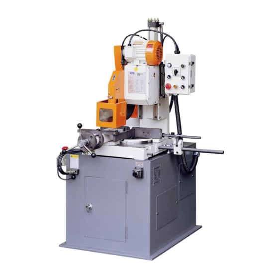
Page 8: Part Name
(3) Part Name Fig.1 B L A D E C O V E R S U P P O R T V I S E C O N T R O L B O X MAIN VISE CYLINDER C U T T I N G S T R O K E A D J U S T D E V I C E... -
Page 9: Layout Drawing
2. Layout Drawing Fig.2... -
Page 10: Installation And Moving
3. Installation and Moving (1) Installation of the Machine CAUTION When you install the machine, please don’t give a severe hit or impact to its main body. Please be careful not to break the gauges, sensors and other fragile important parts on the machine. The location of installation should be safe from vibration and other influence of machines. -
Page 11: Transportation
(2) Transportation WARNING When transport and install machine, please be aware of that there is no worker near the machine. We strongly recommend the expert to use the crane and lift carrier for carry it. When transporting the machine, please use the lift carrier or crane. For lift carrier, the two legs of lift carrier should be placed the below of the stand in order to carry safely. -
Page 12: Cleaning Before Operation
(3) Cleaning Before Operation WARNING In order to remove the rust inhibitor, do not use the metal scrap. This can bring the damage on the surface of machine; therefore it may drop the precise of machine. Also do not clean the surface of machine with toluene or thinner. -
Page 13: Power Source Facility
(5) Power Source Facility DANGER Without plug and outlet, you can connect the line directly to R.S.T. 3 phases line. In this case, the skilled electric engineer must connect. If not, you may hurt or die by the electricity shock. Please check the using voltage supply is appropriate with the machine’s 3 phases voltage. -
Page 14: The Description Of Control Box
4. The description of Control box Fig.4 ◈ Power On When you put on or off the power, please select the switches.(left: on, right: off) When the lamp of select switch is not on, please check the breaker in the control panel. ◈... - Page 15 ◈ Saw Blade(Low/Stop/High) It is Cam Switch. You can adjust the rotation speed of blade by selecting the stage; Low, Stop, High. WARNING If the cam switch is on “Stop” point and put the operation mode on “Auto” mode, the saw blade can be broken. ◈...
- Page 16 ◈ Auto Start One cycle auto operation The procedure is as follow ① Vise Close ② Saw Rotation, Saw Head Down ③ Saw Head Up and Stop, Saw Stop ④ Vise Open ◈ Saw Up/Down In the manual mode, you can raise or down the saw head by selecting this switch.
-
Page 17: Operation
5. Operation (1) The adjustment of Cutting stroke Fig.5 ① Select “Manual” mode on the control panel. ② With Saw Head Up/Down set the cutting stroke by raising the saw head. ◈ Upper Limit Adjustment Fix upper adjust dog to the height that there is no interference of material. -
Page 18: The Adjustment Of Vise Stroke
(2) The adjustment of vise stroke Fig.6 Turn vise handle up to less than 10mm between material and vise and fix it. Generally, around 5mm is the best distance between material and vise. -
Page 19: Angular Cut
(3) Angular Cut In order to work angular cutting, first loosen lock screw, located front sides. Then turn the column right or left with position set handle. The round table moves with column.(There is angular stopper on the left 45° point) When you decide the point, tighten the lock screw.(Fig.7) Fig.7 DANGER... -
Page 20: Fixed Vise Jaw
(4) Fixed Vise Jaws ① DCS-100H Please use fixed vise jaws when you want to cut material less than Ø90mm. If you want to cut Ø90 ~Ø100mm, please remove the fixed vise jaws and operate. In case of angular cutting, please move the fixed vise jaws left or right to avoid the saw blade’s interference. -
Page 21: Saw Blade
(6) Saw Blade DANGER Before install or uninstall the saw blade, make it sure the power plug is off. ① Install/uninstall Saw Blade In order to uninstall the saw blade, first push the stopper that is front of Main shaft box and set the main shaft. Then loosen the fix bolt(M24 Hexagon left screw) which is in the center of blade. -
Page 22: Vise Pressure Adjustment
(7) Vise Pressure Adjustment Fig.10 You can adjust vise pressure by turning the knob of reducing valve(OG- G01-P1), which is pressure control valve. The reducing valve is under right the solenoid valve(SS-G01-E3X-C1) on the hydraulic unit at the backside of machine. -
Page 23: Timer Adjustment
(8) Timer Adjustment Fig.11 T1: (Pressure Switch work), It indicates the time from vise closes to saw head begins to down. T2: It indicates the time when Saw head moves up and stops after cutting to vise open. You can adjust the time by turning scale. -
Page 24: Saw Head Speed Control
(9) Saw Head Speed Control This control valve, which is hydraulic flow control valve, controls the downward speed of Saw Head. To increase the downward speed of Saw Head, turn the control valve clockwise.(fig.12) To decrease the downward speed of Saw Head, turn the control valve anticlockwise. -
Page 25: Cutting Procedure
6. Cutting Procedure WARNING During the operation, do not lean on the machine and touch the round table. ① Turn the power switch on and push the Control on Switch. ② Select the Manual Mode and set the Vise stroke and Saw Head stroke according to the cutting material. -
Page 26: Hydraulic System
7. Hydraulic System Hydraulic Circuit Fig.13... -
Page 27: Parts List
(2) Parts list N o . D e s c r i p t i o n Q ' t y M a k e r Solenoid Valve SS-G01-E3X-R-C1-30 NACIH Solenoid Valve SS-G01-C6-R-C1-30 NACIH Pilot Check Valve OCP-G01-B1-20 NACIH Pilot Check Valve OCP-G01-W1-20 NACIH Pressure S/W... -
Page 28: Electric System
8. Electric System (1) Electric Circuit... - Page 29 Fig.14...
-
Page 30: Part List
(2) Electric Part List No. D e s c r i p t i o n M l Q’ty R e m a r k CIRCUIT BREAKER ABE33/20A MAGNET CONNECTER GMC-12,110V EMPR GMP22-2PD,22A,110V THERMAL OVERLOAD RELAY GTH-22,2.5-4A LIGHT SELECT S/W K30-44,W,110V Push Button K30-21,G110V... - Page 31 No. D e s c r i p t i o n M l Q’ty R e m a r k FLEXIBLE CONNECT GWCZ-22 FLEXIBLE CONNECT GWCZL-22 FLEXIBLE CONNECT BG-22 FLEXIBLE TUBE 22mm CABLE LOCKER HYC-M2 CABLE LOCKER KA-PG-13.5 CABLE LOCKER PLUG 4P20A S/W BRACKET...
-
Page 32: Maintenance
9. Maintenance (1) Chip Scrapper It removes the chips out of pitches of circular saw blade. If it is worn out, replace it. (2) Chip Box The chip box is inside of stand. If it is packed with chips, please get rid of them. -
Page 33: ① Stand Assembly
(4) Assembly DWG. ① Stand Assembly Fig.15... - Page 34 No. D e s c r i p t i o n Q’ty R CHIP BOX ‘ㄷ’ HANDLE WRENCH BOLT LINE BLOCK B HANDLE STAND WASHER WRENCH BOLT REAR COVER WASHER WRENCH BOLT SIDE COVER B WRENCH BOLT WASHER SIDE COVER A THROTTLE V/V BASE WRENCH BOLT FLOW CONTROL V/V...
-
Page 35: ② Table Assembly
② Table Assembly Fig.16... - Page 36 No. D e s c r i p t i o n Q’ty R TABLE Hex. BOLT HANDLE SOCKET HEAD BOLT STOP PIN WRENCH BOLT FIXED VISE JAW(R) FIXED VISE JAW(L) FIXED VISE Hex. BOLT Hex. BOLT SPRING WASHER ROUND TABLE GUIDE ROD STOPPER STOPPER B/K...
-
Page 37: ③ Column Assembly
③ Column Assembly Fig.17... - Page 38 No. D e s c r i p t i o n Q’ty R e m a r k s CONTROL BOX WRENCH BOLT CONTROL BOX B/K WRENCH BOLT COLUMN REAR COVER Hex. BOLT GUIDE WRENCH BOLT COLUMN LIMIT S/W BOX WRENCH BOLT WRENCH BOLT FIXED GUIDE...
-
Page 39: ④ Coolant & Blade Cover Assembly
④ Coolant & Blade cover Assembly Fig.18... - Page 40 No. D e s c r i p t i o n Q’ty R e m a r k s WRENCH BOLT BELT COVER V-BELT MOTOR PULLEY SOCKET HEAD BOLT MOTOR Hex. BOLT SNAP FASTENERS Hex. BOLT COIL SPRING ROD BOLT A CHIP REMOVE ARM CHIP REMOVE ROLLER ROD BOLT B...
-
Page 41: ⑤ Moving Vise Assembly
⑤ Moving Vise Assembly Fig.19 No. D e s c r i p t i o n Q’ty R e m a r k s KNOB HANDLE COLLAR BEARING COVER THRUST BEARING SOCKET HEAD BOLT... - Page 42 No. D e s c r i p t i o n Q’ty R e m a r k s WRENCH BOLT FRONT COVER CYLINDER DUST SEAL O-RING O-RING O-RING PISTON ROD O-RING O-RING DUST SEAL WRENCH BOLT SLIDE BUSH REAR COVER THRUST BEARING MOVING SCREW...
-
Page 43: ⑥ Gear Box Assembly
⑥ Gear Box Assembly Fig.20... - Page 44 No. D e s c r i p t i o n Q’ty R e m a r k s Hex. BOLT SPRING WASHER CUTTER CAP PIN CUTTER CAP 24NT GEAR SHAFT RETAINER BALL BEARING 24NT GEAR SNAP RING BALL BEARING BEARING WASHER LOCK NUT SOCKET HEAD BOLT...
- Page 45 No. D e s c r i p t i o n Q’ty R e m a r k s 11NT GEAR B PULLEY RETAINER WRENCH BOLT BEARING COVER B PLATE SPRING SNAP RING BALL BEARING SNAP RING SNAP RING BALL BEARING BALL BEARING 11NT GEAR A...
Need help?
Do you have a question about the DCS - Series and is the answer not in the manual?
Questions and answers