Table of Contents
Advertisement
Quick Links
Instruction Manual
& Parts List
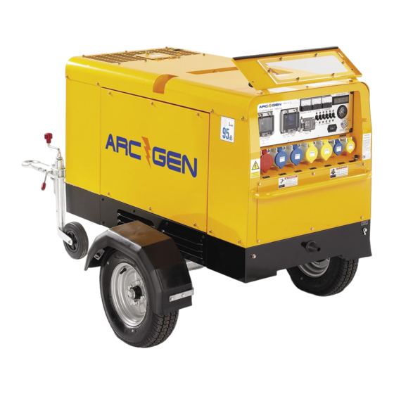
Multi-Voltage Generator
Model: PowerMaker
15MVK
Caution: Do not attempt to operate this machine until
you have read and understood completely
ALL instructions and guidelines contained.
Keep this manual available at all times for
operators and service engineers.
ISSUE DATE: FEBRUARY 2006
1
Advertisement
Table of Contents

Summary of Contents for ArcGen Hilta PowerMaker 15MVK
- Page 1 Instruction Manual & Parts List Multi-Voltage Generator Model: PowerMaker 15MVK Caution: Do not attempt to operate this machine until you have read and understood completely ALL instructions and guidelines contained. Keep this manual available at all times for operators and service engineers. ISSUE DATE: FEBRUARY 2006...
-
Page 2: Table Of Contents
Contents Page Page Numbers Preparations Instrument Names 9-10 Operating Procedures 10-22 Starting and Operations 13-14 Stopping the engine 14-15 Operating Precautions 15-16 Emergency Stop Devices Engine Stop Switch Operating the Generator 17-22 AC Power 17-19 Earth Leakage Relay 18-22 Lubricating Oil, Coolant and Fuel 23-24 Engine Oil Engine Coolant... - Page 3 Contents Page Continued Page Numbers Major Specifications Generator Wiring Diagram 15MVK Engine Wiring Diagrams Outline Drawings 15MVK Parts List and Diagrams 36-71...
- Page 4 For detailed operation and maintenance of the ENGINE, please refer to the “Engine Operation Manual”, supplied by the engine manufacturer. Your machine: Model No: Powermaker 15MVK There may be a difference between the specification detailed in this manual and the actual performance of the machine due to modifications to the machine.
- Page 5 Safety Precautions DANGER: ENSURE GOOD VENTILATION Exhaust from the engine contains substances harmful to the human body. Sufficient change of air is necessary when the machine is used in places with poor ventilation, such as in a tunnel or indoors. Do not direct exhaust to passers by or houses.
- Page 6 Safety Precautions - Continued CAUTION: DURING OPERATION Do not open any of the following items while the generator is running and immediately after the generator has stopped. 1. Radiator Cap Only perform these checks when the engine is cold to avoid injury.
-
Page 7: Preparations
1. Preparations This machine has undergone stringent factory tests and inspections to ensure the machine performs in accordance with its specifications, before being shipped to the end user. As with any piece of motorised machinery, excessive use of brand new machinery may shorten the life of the machine. - Page 8 1. Preparations - Continued 1.3 Notice for Installation (Notice) Make sure the generator is placed on a secure and level surface. When using the generator on an inclined surface, the allowable inclination angle is up to 20 degrees. (Notice) Avoid using the generator in places of high humidity. (Notice) Avoid using the generator in places where surrounding temperature is likely to rise over 40 degrees Celsius.
-
Page 9: Instrument Names
2.2 Name of Components 01. Alternator 02. Diesel Engine 03. Air Cleaner 04. Fuel Tank 05. Fuel Filter 06. Oil filler 07. Oil Filter 08. Oil dipstick 09. Radiator 10. Radiator Reserve Tank 11. Battery 12. Junction Terminal 13. Fuse Reference Powermaker 15MVK... -
Page 10: Operating Procedures
2. Instrument Names - Continued 2.3 Control panel and name of instrument 1. Circuit breaker (for 415V) 13. AC Power output receptacle 2. Circuit breaker (for 110V) (1-phase 240V 16A ) 3. Frequency meter 14. AC Power output receptacle 4. A.C Ammeter (1-phase 110V 16A) 5. - Page 11 3. Operating Procedures - Continued (Notice): Grades of lubricating oil (service classification) CA, CB, CC, CD - Diesel Engine classification. (Notice): Selection of engine oil viscosity. Use oil viscosity most suitable to the temperature under which the machine is used. For example, SAE30 (oil for summertime use).
- Page 12 3. Operating Procedures - Continued DANGER: FIRE PREVENTION Fuel and oil are inflammable. Keep inflammable material away from the machine, never smoke while refuelling and never refuel during operation. 5. Battery Check Always ensure the level of battery fluid is maintained above the low level mark. If the battery fluid is low, distilled water should be immediately supplied to the battery.
-
Page 13: Starting And Operations
3. Operating Procedures - Continued 3.1 Starting and Operating Before starting the machine, the pre-starting safety checks must be completed. In addition, do a general survey of the area surrounding the machine making sure the area is safe, air vents of the machine are not blocked and the exhaust can be freely discharged. -
Page 14: Stopping The Engine
3. Operating Procedures - Continued 5) Carefully check the engine for abnormal vibration (noise), oil leakage, fuel leakage, cooling water leakage and air leakage. If the machine is operating normally, set the “circuit breaker” to the ON position in order to supply electricity to the load. (Notice): While the machine is operating do not have any obstacles within one meter radius from the machine. -
Page 15: Operating Precautions
3. Operating Procedures - Continued (Notice): In the unlikely occurrence of the engine not stopping when the key is turned to the “Off” position, there is a way of stopping the generator. Please refer to the following diagram and explanation. In order to stop the machine in this situation, you must turn the fuel filter cock to the “closed”... -
Page 16: Emergency Stop Devices
3. Operating Procedures - Continued 3.4 Emergency stop devices. The generating set is equipped with the following “Emergency Stop” devices. • When one of the emergency stop devices is activated, the engine will stop automatically and the control panel will indicate where the problem is. The operator must turn the starter switch to “stop"... -
Page 17: Operating The Generator
4. Operation of the Generator 4.1 AC Power This machine is equipped with single phase and three phases output generating capabilities. (Notice): In connecting a load, make sure the correct size of cable and plugs are used on the appropriate output terminal. -
Page 18: Earth Leakage Relay
4. Operation of the Generator - Continued DANGER: NO CONNECTION TO DOMESTIC WIRING Connection to domestic wiring is illegal and very dangerous because it may cause electric shocks and damage to the generator. 5. The following diagrams illustrate how to connect 1-phase and Single-phase loads to the generators output terminal. - Page 19 4. Operation of the Generator - Continued • When the earth leakage relay is activated, the operator should immediately locate the leakage and repair it. Once the repairs have been completed, you should press the reset button on the earth leakage relay or stop the engine and then turn the circuit breaker on again.
- Page 20 4. Operation of the Generator - Continued Table 1 setting of the related current 1 (Notice): This mode (switch 1 at “ON”) is given precedence to other switches 2 ~ 8. Slide switch mode current switch 30mA 0.04 sec. Or less 100mA 200mA 500mA...
- Page 21 4. Operation of the Generator - Continued Table 2: Setting of the tripping time Set time Slide switch mode Switch 0.04 sec. Or less 0.3 sec. (0.2~ 0.36) 0.5 sec. (0.4 ~ 0.6) 1 sec. (0.8 ~ 1.2) 2 sec. (1.3 ~ 2) How to change the settings: 1.
- Page 22 4. Operation of the Generator - Continued (3) How to Use and Test the Earth Leakage Relay The following descriptions allow you to make sure the earth leakage relay is functioning correctly. (1) Perform a periodic check on the earth leakage relay to ensure it is operating correctly, in accordance with the following instructions •...
-
Page 23: Lubricating Oil, Coolant And Fuel
5. Lubricating Oil, Cooling Water and Fuel 5.1 Engine Oil Open Air Temp (°C) SAE20 SAE30 E5W20 SAE10W30 SAE15W40 • The lubricating oil used influences engine performance, starting characteristics and ultimately the life of the engine. We recommend that an appropriate, good quality lubricating oil be used. -
Page 24: Fuel
5. Lubricating Oil, Cooling Water and Fuel - Continued (Notice): The LLC should be changed at least every 2 years. 3) The total cooling water capacity is 2.2L (This does not include the cooling water reserve tank) A) For the proper use of LLC, carefully follow the instructions given by the LLC manufacturer. -
Page 25: Maintenance
6. Maintenance 6.1 Maintenance for the Initial 50 hours 1) Oil Change An oil change must be done after the initial 50 hours of operation. Thereafter, an oil change is required for each 200 hours of operation. (a) To change the engine oil take out the engine oil drain plug and wait until all the old oil has been drained. -
Page 26: Maintenance Check Every 200 Hours Of Operation
6. Maintenance - Continued (Notice): After cleaning the air element, check to see whether there is any damage to the element. If there is any damage replace the damaged element with a new element. 6.3 Maintenance check every 200 hours of operation Change the engine oil Lubricant capacity 5.1 L Change the oil filter Cartridge : Part No. -
Page 27: Maintenance Check Every 1000 Hours Of Operation
6. Maintenance - Continued 6.7 Maintenance Check Every 1000 Hours of Operation. (1) Clean the inside of the fuel tank. 6.8 Other Checks and Maintenance (1) Change the nylon or rubber pipes. In cases where the nylon or rubber pipes have become hard, deterioration of the rubber has taken place, replace it. -
Page 28: Troubleshooting
7. Troubleshooting Check point No. Engine fails to start → Starter rotates 1, 2, 3, 4, 8 → 5, 6, 8 Starter fails to rotate 2, 3, 4, 8, 9 Something wrong with engine 8, 10, 11 Insufficient output of engine 1, 2, 3, 4, 7, 9, 11, 12, 13, 14 Engine suddenly stops during operation CHECK POINT... -
Page 29: Storage Of Machines
8. Storage Of Machine It is very important to carry out the prescribed maintenance and inspection in order to maximise the machine’s useful life and performances. • (1) Long term storage. For long term storage of the machine, the battery cable terminal ( - ) must be disconnected from the battery. -
Page 30: Major Specifications
9. Major Specifications Spec \ Model 15MVK Ac Generator Type Rotating - field, protection type synchronous gene. 3 - Phase Frequency (Hz) Rated output (kVA) Rated Voltage (V) 415/240 Rated Current (A) 20.9 Number of Phases 3-phase 4-phase Power Factor Excitation Brushless type (with AVR) Number of poles... -
Page 31: Generator Wiring Diagram 15Mvk
10. Generator Wiring Diagram 15MVK... -
Page 32: Engine Wiring Diagrams
11. Engine Wiring Diagram... -
Page 33: Outline Drawings 15Mvk
12. Outline Drawing 15MVK... - Page 35 CATALOGUE 15MVK How to use the parts list 1. This part list covers the parts for AC Generator model, Powermaker 15MVK. 2. When placing orders specify the following details: a) Model number and serial number b) Parts number and part name c) Quantity required 3.
- Page 37 Index Name Pages Generator Set 38 - 39 Generator Assembly 40 - 43 Control Panel 44 - 47 Output Terminal Assembly 48 - 49 Engine and radiator Assembly 50 - 53 Battery Assembly 54 - 55 Muffler Assembly 56 - 57 Fuel Tank Assembly 58 - 61 Bonnet Assembly –...
- Page 38 Generator Set...
- Page 39 Generator Set Item No: Part Names, Remarks Generator Assembly Reference :P 40-43 Control Panel Assembly Reference :P 44-47 Engine Radiator Assembly Reference: P 50-53 Battery Assembly Reference :P 54-55 Muffler Reference :P 56-57 Fuel Tank Assembly Reference: P 58-61 Bonnet Assembly Reference: P 62-69 Name plate Assembly Reference: P 70...
- Page 40 Generator Assembly...
- Page 41 Generator Assembly Item No: Part No: Part Name: Quantity 41100 00403 Rotor Assembly 06018 20037 Rectifier 06018 22638 Surge Absorber 00712 06307 Bearing 00800 00035 Snap ring 00124 10030 Hex. Head Bolt 41111 00103 00171 08025 Hex. Head Bolt 78113 15102 End Bracket 85113 41003 Armature Assembly...
- Page 42 Generator Assembly - Continued...
- Page 43 Generator Assembly - Continued Item No. Part No. Part Name . Quantity 00171 06040 Hex. Head Bolt 00379 06000 Hex. Nut 41331 00703 Generator Foot 41331 00603 Generator Foot 00123 10025 Hex. Head Bolt 08050 83904 Rubber Suspension 02070 10000 Hex.
- Page 44 Control Panel Assembly...
- Page 45 Control Panel Assembly Item No: Part No: Part Name: Quantity 02250 02703 Control Panel 00218 06030 Machine Screw 06018 00455 Frequency Meter 06018 05749 AC Ammeter 06018 00285 AC Voltmeter 06018 09070 Circuit Breaker 22A 00210 04035 Machine Screw 00400 04000 Spring Washer 00421 04000 Plain Washer...
- Page 46 Control Panel Assembly - Continued...
- Page 47 Control Panel Assembly - Continued Item No. Part No. Part Name . Quantity 06018 10523 Indicator Assembly 06018 10830 Bulb 06021 25055 Fuel Gauge 06018 00682 Hour Meter 06018 15759 Terminal Board 00271 05025 Machine Screw 02686 00004 Resistor 00271 04012 Machine Screw 06018 23204 Rectifier...
- Page 48 Output Terminal Assembly...
- Page 49 Output Terminal Assembly Item No: Part No: Part Name: Quantity 06018 15426 Terminal Board 00271 04025 Machine Screw 87018 60004 Set Board, output terminal 85018 67304 Set Board, output terminal 78118 61004 Output Terminal 08018 30604 Hex. Head Bolt 00400 08000 Spring Washer 00414 08000 Plain Washer...
- Page 50 Engine and Radiator Assembly...
- Page 51 Engine And Radiator Assembly Key No Part No Part Name Quantity 09252 00254 Engine 06020 11479 Fan Belt 1 - 1 06020 41174 Cartridge, oil filter 43052 00504 Engine Foot 00124 10025 Hex. Head Bolt 76054 19004 Rubber Suspension 02070 10000 Hex.
- Page 52 Engine and Radiator Assembly – Continued...
- Page 53 Engine and Radiator Assembly - Continued Key No Part No Part Name Quantity 06055 15139 Hose Band 06055 15027 Hose Band 15020 25103 Drain Joint, oil 16220 14103 Drain Joint, water 08020 11104 Plug 01500 00018 O Ring 00169 06016 Hex.
- Page 54 Battery Assembly...
- Page 55 Battery Assembly Item No. Part No Part name. Quantity 01691 05524 Battery 87222 51004 Battery Sheet 75522 53004 Battery Band 78722 51004 Battery Bolt 00378 06000 Wing Nut 00400 06000 Spring Washer 00416 06000 Plain Washer 06022 20312 Terminal Assy + VE 06022 20313 Terminal Assy - VE 06022 20600...
- Page 56 Muffler Assembly...
- Page 57 Muffler Assembly Key No Part No Part Name Quantity 43321 01103 Muffler 00169 08020 Hex Head Bolt 43350 01403 Exhaust Pipe 06023 20153 Gasket 15023 36004 Gasket 02070 08000 Hex. Nut 00169 08035 Hex head Bolt 43351 00304 Outlet Pipe 91022 00004 Pipe Band 91022 00304...
- Page 58 Fuel Tank Assembly...
- Page 59 Fuel Tank Assembly Key No: Part No: Part Name: Quantity 43650 00903 Fuel Tank 08101 05800 Cap Fuel Tank 08101 05900 Fuel Filter 06055 01082 Sender, fuel gauge 19243 00184 Gasket 00229 05015 Machine Screw 03653 00903 Bracket, fuel tank 00169 08020 Hex.
- Page 60 Fuel Tank Assembly - Continued...
- Page 61 Fuel Tank Assembly - Continued Key No Part No Part Name Quantity 06055 13134 Suction Hose 06055 13116 Suction Hose 06055 14027 Return Hose 06055 14064 Return Hose 06055 15070 Hose Band 06055 15072 Hose Band...
- Page 62 Bonnet Assembly - Part 1...
- Page 63 Bonnet Assembly - Part 1 Key No Part No Part Name Quantity 04150 02502 Base 04950 00103 Lining 44151 00404 Floor Panel 00169 06016 Hex Head Bolt 04552 00303 Splasher Panel 04552 00203 Splasher Panel 00169 06016 Hex Head Bolt 04250 01102 Front Frame 04951 01103...
- Page 64 Bonnet Assembly - Part 1 Continued...
- Page 65 Bonnet Assembly - Part 1 Continued Key No Part No Part Name Quantity 04453 02804 Cover, rear frame 04953 01004 Lining 00169 06016 Hex. Head Bolt 04650 00902 Roof Panel 04955 00304 Lining 00169 06016 Hex. Head Bolt 78151 65004 Cover 78151 65504 Rubber Sheet...
- Page 66 Bonnet Assembly - Part 1 Continued...
- Page 67 Bonnet Assembly - Part 1 Continued Key No Part No Part Name Quantity 78350 88004 Collar 00171 08020 Hex. Head Bolt 08450 41904 Grommet 85118 64604 Plate 00169 06016 Hex. Head Bolt 44458 00104 Ring Pin...
- Page 68 Bonnet Assembly - Part 2...
- Page 69 Bonnet Assembly - Part 2 Key No Part No Part Name Quantity 02283 00820 Rubber Seal 02283 00465 Rubber Seal 02219 00106 Rubber Seal 02219 00410 Rubber Seal 02203 02450 Rubber Seal 03180 00810 Rubber Seal 03180 00760 Rubber Seal 02292 00240 Rubber Seal 02292 00600...
- Page 70 Name Plate Assembly Key No Part No Part Name Quantity 08006 60204 Plate : AC110v 16306 45004 Decal ; Oil Drain 16306 47004 Decal ; Coolant Drain 16306 80004 Decal ; Use #2 Diesel fuel only 08006 66504 Decal ; AC240v 08006 89404 Decal ;...
- Page 71 CE Warning Decals...
Need help?
Do you have a question about the PowerMaker 15MVK and is the answer not in the manual?
Questions and answers