Table of Contents
Advertisement
Quick Links
Advertisement
Table of Contents

Summary of Contents for FOCALSPEC LCI1220
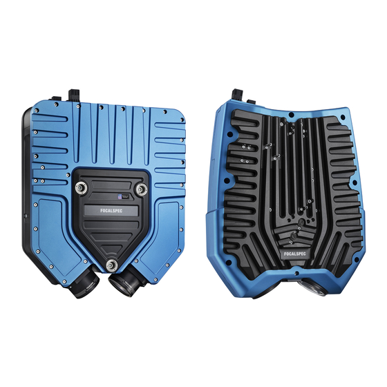
- Page 1 FOCALSPEC LINE CONFOCAL SENSORS LCI1220 & LCI1620 USER GUIDE Version 1.0...
- Page 2 2019-09-30 FOCALSPEC User quide LCI1220-1620 v1.0 1/31 Version history Version Status Date Author Comments Approved 30.9.2019 Esa Kalistaja First version FocalSpec Oy • Elektroniikkatie 13, FI-90590 Oulu • www.focalspec.com...
-
Page 3: Table Of Contents
10 External Trigger Configurations..............20 11 Sensor Warming Up ..................21 12 Preparing Measurement Setup ............... 21 13 Getting Started ....................23 14 Troubleshooting ..................... 29 15 Support ......................30 16 Abbreviations ....................30 FocalSpec Oy • Elektroniikkatie 13, FI-90590 Oulu • www.focalspec.com... -
Page 4: About This Document
3/31 1 About this Document This document is user guide of sensors LCI1220 and LCI1620. Sensors LCI401, LCI1200, LCI1201 and LCI1600 are covered by separate guide. FocalSpec Software Development Kit (FSSDK) and the API documentation can be found after FSSDK installation from folder: C:\Focalspec\FocalSpec Software Development Kit\Manual. -
Page 5: Proper Use
Ambient temperature range: +15 ºC … +35 ºC. 2.4 CE Marking FocalSpec Oy has confirmed that these products comply with the essential requirements of the applicable EC Directive, based on the following specifications. FocalSpec Oy • Elektroniikkatie 13, FI-90590 Oulu • www.focalspec.com... -
Page 6: Technical Data
IP55 IP30 * Z repeatability is the standard deviation of Z measurements using the FocalSpec target at the specified reference distance ** Maximum speed is maximum frequency to measure region of interest (ROI) with the depth 0.4 mm on full... -
Page 7: Connecting To Pc
USB drive folder “hardware”. The position and orientation of the optical profile is shown in an enlarged detail image for each model. The X, Y, Z origin in each STEP file is placed into the middle of the optical profile. FocalSpec Oy • Elektroniikkatie 13, FI-90590 Oulu • www.focalspec.com... - Page 8 2019-09-30 FOCALSPEC User quide LCI1220-1620 v1.0 7/31 Figure 2. Installation and mounting of LCI1220. FocalSpec Oy • Elektroniikkatie 13, FI-90590 Oulu • www.focalspec.com...
- Page 9 2019-09-30 FOCALSPEC User quide LCI1220-1620 v1.0 8/31 Figure 3. Installation and mounting of LCI1620. FocalSpec Oy • Elektroniikkatie 13, FI-90590 Oulu • www.focalspec.com...
-
Page 10: Handling Optical Cable And Sfp+ Modules
Don’t let the cable bend more than this. This applies to the whole length of the cable and it is especially important to pay attention to computer end of the cable as it is more flexible. FocalSpec Oy • Elektroniikkatie 13, FI-90590 Oulu • www.focalspec.com... -
Page 11: Installing Sfp+ Module And Optical Cable
3. Push the lock handle down on the SFP+ module (step 1). This is the open position. This is done because the SFP+ module might be used with some SFP+ slots which FocalSpec Oy • Elektroniikkatie 13, FI-90590 Oulu • www.focalspec.com... -
Page 12: Detaching Sfp+ Module From Optical Cable
1. Press the lock tab down in optical cable connector (step 1). 2. Pull the cable out of SFP+ module (step 2). 3. Place protective caps on the optical cable connector and SFP+ module. FocalSpec Oy • Elektroniikkatie 13, FI-90590 Oulu • www.focalspec.com... -
Page 13: Electrical Connections
12/31 8 Electrical Connections LCI1220 and LCI1620 sensors are powered by using a PushPull type 4-pin cable with Harting Power connector. For input signals which can be used for synchronization purposes 10-pin PushPull type cables with Harting Signal Connectors is used. The sensor communicates with PC via Optical cable with SFP+ 10G transceiver modules. - Page 14 Power LED indicates with green light that power is ON and supply voltage level is in correct range. Red indicates that supply power is over the correct supply range and then the device will not power up. FocalSpec Oy • Elektroniikkatie 13, FI-90590 Oulu • www.focalspec.com...
- Page 15 2019-09-30 FOCALSPEC User quide LCI1220-1620 v1.0 14/31 Table 2. Indicator LEDs FocalSpec Oy • Elektroniikkatie 13, FI-90590 Oulu • www.focalspec.com...
-
Page 16: Input And Output Description
24 V (21 V – 28 V) / 2.3 A 24VDC Power Ground Red ring Cable Cable shield (connect to Terminal Shield system GND) Figure 8. Power cable NOTE 1: Connect the power cable ring terminal to system GND FocalSpec Oy • Elektroniikkatie 13, FI-90590 Oulu • www.focalspec.com... - Page 17 Input 6 (5V & 24 V) Output 1 24 V Output 1 (250 mA) Black Output 2 24 V Output 2 (250 Violet Digital GND (for Output use) I/O 1 PINOUT Figure 9. Signal cable FocalSpec Oy • Elektroniikkatie 13, FI-90590 Oulu • www.focalspec.com...
- Page 18 Input signal current Min 2.7 mA Input signal current Max 15 mA Output signal current Max (2 output pins) 250 mA Figure 10. Optical cable with SFP+ modules in both ends FocalSpec Oy • Elektroniikkatie 13, FI-90590 Oulu • www.focalspec.com...
- Page 19 2019-09-30 FOCALSPEC User quide LCI1220-1620 v1.0 18/31 Figure 11. Optical cable SFP+ module FocalSpec Oy • Elektroniikkatie 13, FI-90590 Oulu • www.focalspec.com...
- Page 20 Figure 12. Example wiring for sensor connection NOTE 1: Connect the power cable ring terminal to system GND NOTE 2: Ensure that the sensor mount has the same ground potential as the sensor itself. FocalSpec Oy • Elektroniikkatie 13, FI-90590 Oulu • www.focalspec.com...
-
Page 21: External Trigger Configurations
Application examples include: synchronizing the profile measurement into a certain signal of a production process or combining profiles into 3D point clouds based on the trigger index. Enabling external and internal triggering is explained in the “FocalSpec Software Development Kit”. Configuring inputs is done programmatically using corresponding FSSDK parameters and values 1-4 as shown in the table below. -
Page 22: Sensor Warming Up
• The target on the reference sample holder must not be touched. Keep the sample clean and if needed, use compressed air for cleaning, do not use liquid, etc. FocalSpec Oy • Elektroniikkatie 13, FI-90590 Oulu • www.focalspec.com... - Page 23 2019-09-30 FOCALSPEC User quide LCI1220-1620 v1.0 22/31 Figure 15. Reference sample holders of LCI1220 (left) and LCI1620. FocalSpec Oy • Elektroniikkatie 13, FI-90590 Oulu • www.focalspec.com...
-
Page 24: Getting Started
Lay down the sensor carefully on a table with Focalspec label up and mounting holes down. Refer to chapter “Preparing Measurement Setup”. LCI1620 LCI1220 Check the connector order of the sensor. FocalSpec Oy • Elektroniikkatie 13, FI-90590 Oulu • www.focalspec.com... - Page 25 Ethernet cap is loose, store it for possible future use. Dust caps removed from POWER, I/O 1 and Ethernet. Plug 10-pin signal connector into I/O1 port. Yellow marks indicate correct orientation. FocalSpec Oy • Elektroniikkatie 13, FI-90590 Oulu • www.focalspec.com...
- Page 26 Plug optical cable with SFP+ module into Ethernet port. Yellow marks indicate correct orientation. Optical cable properly mated. Plug the SFP+ module of the optical cable’s other end into computer. FocalSpec Oy • Elektroniikkatie 13, FI-90590 Oulu • www.focalspec.com...
- Page 27 5. Right-click Local Area Connection (the adapter connected to the sensor in step 3.) and select Properties. 6. Open Configure 7. Select Jumbo Packet and select 9014 Bytes 8. Click OK. FocalSpec Oy • Elektroniikkatie 13, FI-90590 Oulu • www.focalspec.com...
- Page 28 Windows Firewall rules, which allow the example application to communicate with the sensor. If you are using another firewall, allow these programs after the installer has finished: GuiExample\bin\Release\GuiExample.exe FocalSpec Oy • Elektroniikkatie 13, FI-90590 Oulu • www.focalspec.com...
- Page 29 The application controls are explained in FocalSpec Software Development Kit (FSSDK) and the API documentation which can be found after FSSDK installation from folder: C:\Focalspec\FocalSpec Software Development Kit\Manual. FocalSpec Oy • Elektroniikkatie 13, FI-90590 Oulu • www.focalspec.com...
-
Page 30: Troubleshooting
Windows firewall. To validate this, open Windows firewall and check that the rules are created into “Inbound Rules” with names “FocalSpec SDK GUI Example”. If you have another firewall, allow GuiExample.exe d. Check IPv4 address settings for the connected Ethernet adapter. To validate this, refer to the step 10 of chapter “Getting Started”. -
Page 31: Support
Average Intensity LED Pulse Width [µs] monitor text box, which indicates if low, ok, too high. 15 Support For further assistance, please do not hesitate to contact FocalSpec: support@focalspec.com 16 Abbreviations Computer-aided Design Graphical User Interface Line Confocal Imaging Light-Emitting Diode...
Need help?
Do you have a question about the LCI1220 and is the answer not in the manual?
Questions and answers