
Summary of Contents for AZALEA AVIATION SPYDER 100 HP
- Page 1 AZALEA AVIATION, LLC AZALEA AVIATION, LLC 100/120 100/120 HP SPYDER HP SPYDER ENGINE ASSEMBLY MANUAL ENGINE ASSEMBLY MANUAL ENGINE ASSEMBLY MANUAL AzaleaAviation.com...
-
Page 2: Table Of Contents
SPYDER 100/120 HP Engine Assembly Manual TABLE OF CONTENTS Section and Description 1. Introduction 2. Case Assembly (with IFB Update) 3. Accessory Housing Assembly 4. Accessory / Alternator Installation 5. Starter/Oil Cover Plate Installation 6. Piston/Cylinder Assembly 7. Piston/Cylinder Final Installation 8. -
Page 3: Introduction
For information about these procedures you can purchase the SPYDER Engine Teardown and Preparation Manual through Azalea Aviation or join one of our engine clinics that are held periodically. -
Page 4: Accessory Housing Assembly
Loctite Lithium Grease Copper Spray adhesive Parts Required: Accessory Housing Oil Pump Kit (6) Stainless Drilled 10-32 Allen Screws Oil Pressure Valve Nut – spring - piston Oil Pump Cover Rear Seal Section 3 – 1 Azalea Aviation Copyright 2014... - Page 5 If the gears are tight then a thicker gasket may have to be used. Once all is inspected then safety the bolts with standard .030 safety wire if they have drilled heads. (Fig 3) Section 3 – 2 Azalea Aviation Copyright 2014...
- Page 6 Fig 1. – Checking clearance Fig 2. – Installing Cover plate Section 3 – 3 Azalea Aviation Copyright 2014...
- Page 7 (loctite applied) in the order shown. (Fig 4) Tighten the nut to proper torque. (10 ft/lbs) If drilled, safety the nut to the housing. Fig 4. – Oil Pressure Relieve valve parts Section 3 – 4 Azalea Aviation Copyright 2014...
- Page 8 Notes: If you choose to install the High Volume Oil pump kit be sure to follow the instructions included in the kit. The use of a High Volume Oil pump is not detrimental to the engine if installed correctly. Section 3 – 5 Azalea Aviation Copyright 2014...
- Page 9 Large socket for gear installation Sealants Required: Copper spray Loctite (red and green) Lithium Grease Parts Required: Case assembly Drive gears (4 parts) Accessory bolts (7) Accessory housing 3/8” washers and nuts Alternator Kit (seen below) Section 4 – 1 Azalea Aviation Copyright 2014...
- Page 10 (Do not install the bolt at the 4 o’clock position yet. Install three of the four washers and 3/8 nuts onto the studs. Leave the left one open. (Fig 2) Torque the hardware to the proper specifications. (13 ft/lbs) Section 4 – 2 Azalea Aviation Copyright 2014...
- Page 11 Place onto the end of the crankshaft and using a dead blow hammer tap into place. Install the large washer and bolt using red Loctite and torque to 50 -60 Section 4 – 3 Azalea Aviation Copyright 2014...
- Page 12 TDC mark on the drum is in the proper location. Otherwise turn the crankshaft until the #1 rod journal is at the TDC position and make sure the mark on the alternator drum in near the timing marks on the housing. Section 4 – 4 Azalea Aviation Copyright 2014...
- Page 13 Copper spray Pipe Sealant Red Loctite Parts Required: Case with Rear Alternator attached Oil Cover Plate and hardware Starter Ring Gear Lower Starter bracket and hardware Oil Cooler block off and hardware Section 5 - 1 Azalea Aviation Copyright 2014...
- Page 14 Remove the ring gear and bolt the Starter and lower bracket into position using Loctite on the bolts/nuts. (Figure 4) Reattach the Ring gear using red Loctite on the bolts and torquing to 30 ’lbs. Section 5 - 2 Azalea Aviation Copyright 2014...
- Page 15 Fig. 2 – Block Off Plate Installed Fig. 3 – Ring gear to Bendix clearance Section 5 - 3 Azalea Aviation Copyright 2014...
- Page 16 Fig. 5 – Starter and Ring Gear Finally Bolted Be sure to rotate the crankshaft and check for clearance and interference. Pulses felt during the rotation that is caused by the magnets in the alternator. Onto the next step! Section 5 - 4 Azalea Aviation Copyright 2014...
- Page 17 (Fig 2) If the connecting rod nuts are tightened, loosen them at this time. Remove the wrist pin from the piston, lubricate it lightly with oil and reinsert it to check for freedom of Section 6 - 1 Azalea Aviation Copyright 2014...
- Page 18 Always check the arrow direction on the pistons that they correspond correctly to the numbered rod and installation. Fig. 2 – Rod Clamped into vise Section 6 - 2 Azalea Aviation Copyright 2014...
- Page 19 Fig. 3 – Heating up Rod small end (brownish color) Fig. 4 – Inserting Rod pin using tool – quickly and smoothly Section 6 - 3 Azalea Aviation Copyright 2014...
- Page 20 45 degree crosshatch. The cylinder should be cleaned and painted on the fins. The rods should be balanced, stock forged stroker rods with ARP bolts or new forged rods (available through Azalea Aviation). Section 6 - 4...
- Page 21 Remove the cylinder/piston assembly from the assembly tool and proceed to the next cylinder and piston. (Fig 5) Fig. 1 – Rings ready for Installation Section 6 - 5 Azalea Aviation Copyright 2014...
- Page 22 Fig. 2 – Rings installed Fig. 3 – Cylinder in alignment Fixture - (make your own or call Azalea Aviation for rental/plans to build) Section 6 - 6 Azalea Aviation Copyright 2014...
- Page 23 Fig. 4 - Install piston in correct orientation and compress rings Fig. 5 – Remove the wooden block and firmly tap the piston into cylinder Section 6 - 7 Azalea Aviation Copyright 2014...
- Page 24 Finished and ready for next step! Section 6 - 8 Azalea Aviation Copyright 2014...
-
Page 25: Piston/Cylinder Assembly
Sealants: Copper spray ARP grease Parts Required: Case assembly Piston/Cylinder assemblies (6) Connecting rod bearing kit Cylinder base gaskets (6) Cylinder baffles and clips Inspect condition and quality of parts (Fig 1) Section 7 - 1 Azalea Aviation Copyright 2014... - Page 26 (Fig 3) Remove the rod cap from cylinder #1 and install the rod bearing shells onto the cap and rod. Apply an even coat of oil on the bearings. (Fig 4) Fig 2. – Number the cylinder locations for ease Section 7 - 2 Azalea Aviation Copyright 2014...
- Page 27 Fig 3. - Install rod bearing shell and copper base gasket on cylinder Fig 4. – Oiling bearing shell Section 7 - 3 Azalea Aviation Copyright 2014...
- Page 28 Use the torque wrench and tighten the rod nuts in two stages up to 28 ‘lbs. (Fig 6) Fig. 5 – Installing a Piston/Cyl/Rod assembly in a 100 HP engine Fig. 6 – Cap in place and ready to torque Section 7 - 4 Azalea Aviation Copyright 2014...
- Page 29 6) Once all the cylinders are in position and held securely (loosely install other head) rotate the engine over a couple times to check for binding. (Fig 9) Clean up the table and prepare for the next step! Fig.7 – Cylinders 1,3,5 installed Section 7 - 5 Azalea Aviation Copyright 2014...
- Page 30 Fig. 8 – Installation of Baffle and clips (Notice the ¾” assembly board under the case to provide clearance for the camshaft gear) Fig. 9 - Installing head loosely to check for smooth rotation of parts. (note: no IFB in this installation picture) Section 7 - 6 Azalea Aviation Copyright 2014...
- Page 31 (Fig 2) Fig 1. Use the same procedures concerning checking bearing sizes and lubrication when installing as in the 100 HP section. Fig 2. Section 7 - 7 Azalea Aviation Copyright 2014...
- Page 32 Install the other snap ring to lock the wrist pin in place. Push the cylinder into the case. Once you have three cylinders installed on one side, install the baffle and loosely install a head to hold into position. Section 7 - 8 Azalea Aviation Copyright 2014...
-
Page 33: Cylinder Head Installation
Proper valve work, cc’ing of the combustion chamber, selection of appropriate head and base gaskets should be done with thought and care. More information is available through Azalea Aviation and internet sources concerning these procedures. Section 8 - 1... - Page 34 Apply lithium grease to the pushrod tube sealing surface of the lifter bores. Apply antiseize to the threads of the cylinder head studs. (Fig 4) Fig. 2 – Cam lube on lifters – ready to oil Section 8 - 2 Azalea Aviation Copyright 2014...
- Page 35 (Fig 5) and gently slide the head over the studs and seat against the cylinders. Install the upper cylinder nuts and washer finger tight. (Fig 5) Section 8 - 3 Azalea Aviation Copyright 2014...
- Page 36 Apply lithium grease to the o-rings and slide them onto the bolts. (Fig 6) The “U” on the plates should face outward. Fig. 6 – Rocker shaft installed on plate with o-ring Section 8 - 4 Azalea Aviation Copyright 2014...
- Page 37 (Fig 7) Insert the tube into the lifter bore. Use the 9/16” socket to push the pushrod tube into position. (Fig 8) Fig. 7 – Installing pushrod tube Fig. 8 – Pushing pushrods into position Section 8 - 5 Azalea Aviation Copyright 2014...
- Page 38 This will reduce the amount of “smoking” the engine will do at startup. Also, a clean engine is a “goodly” engine. Section 8 - 6 Azalea Aviation Copyright 2014...
- Page 39 Heads are installed and torqued – On to the valve train…. Section 8 - 7 Azalea Aviation Copyright 2014...
- Page 40 Loctite Parts Required: Pushrods (12) Rockers (12) Grooved balls (12) Rocker shaft nuts (12) Valve covers (2) Valve cover gaskets (2) Valve cover clips (8) Valve cover bolts (8) Pushrods and rockers Section 9 - 1 Azalea Aviation Copyright 2014...
- Page 41 Apply oil to the grooved ball and to the rocker. Assemble the rocker, grooved ball and nut as shown and install. ( Fig 2) Tighten only until the end of the nut is even with the rocker shaft. Proceed will all twelve assemblies. Section 9 - 2 Azalea Aviation Copyright 2014...
- Page 42 Fig. 1 – Inserting pushrod into guide plate Fig. 2 – Rocker assembly Section 9 - 3 Azalea Aviation Copyright 2014...
- Page 43 TDC Compression stroke. The flat of the crankshaft will be horizontal and connecting rod fully extended into the cylinder. (Fig 4) The timing mark on the alternator drum should be pointing to the “0” mark on the rear housing. Section 9 - 4 Azalea Aviation Copyright 2014...
- Page 44 The pushrod will suddenly be harder to rotate. At this point TIGHTEN the nut ¾ of turn. Now repeat this step for the other rocker for cylinder #1. (Fig 5) Section 9 - 5 Azalea Aviation Copyright 2014...
- Page 45 Apply Loctite to the threads of the valve cover bolts and install with the valve cover clip. Tighten to 10 “ lbs. (that’s inch pounds!)…Once the sealant has begun to harden..a couple hours… torque the screws to 40 “ lbs. Fig 6. Section 9 - 6 Azalea Aviation Copyright 2014...
- Page 46 A 120 HP engine with valve train work finished and up on rotator stand…. Section 9 - 7 Azalea Aviation Copyright 2014...
-
Page 47: Oil Pan And Dipstick Installation
Check all parts for condition and quality. There are a couple different oil pans on the market that are usable including a modified stock. We use a deep oil pan that adds a quart of oil. This pan necessitates a modified oil pickup. Section 10 - 1 Azalea Aviation LLC, Copyright 2014... - Page 48 Rubber mallet and tap the tube into position in the case. (Fig2) Trim the length of the Tube if necessary for your installation. Trimming and marking the dipstick will be done later. Section 10 - 2 Azalea Aviation LLC, Copyright 2014...
- Page 49 Check that the holes on the pan line up with the holes on the case and adjust if necessary. Some hardware kits have studs and nuts. Insert the studs with Loctite before installing the pan. If the kit comes with bolts then apply Loctite to Section 10 - 3 Azalea Aviation LLC, Copyright 2014...
- Page 50 The oil drain plug typically comes with a copper washer as a gasket. Use torque chart for proper torque. Section 10 - 4 Azalea Aviation LLC, Copyright 2014...
- Page 51 Final Pan Installation. This is showing our HD cast aluminum pan. It allows you to place the engine on the ground without fear of damaging the pan. Some pans are very lightweight and thin and will require that the engine be supported. Section 10 - 5 Azalea Aviation LLC, Copyright 2014...
-
Page 52: Top Cover Installation
Install the AN-8 pipe fitting onto the front of the Starter bracket. Use some pipe sealant on the threads . Also install the similar fitting onto the IFB housing if not already installed. (Fig1) Fig 1 – Top cover and fitting Section 11 - 1 Azalea Aviation LLC, Copyright 2014... - Page 53 The IFB oil line will have a clamp that secures it to the top cover near the front. This screw will typically be longer for that reason, as well as any that are used for Plenum installation. Section 11 - 2 Azalea Aviation LLC, Copyright 2014...
- Page 54 John finalizing his installation – a good view of the oil line and top cover. Section 11 - 3 Azalea Aviation LLC, Copyright 2014...
-
Page 55: Ignition Installation
Ignition Installation Tools Required: 9/16” Wrench Sealants: Parts Required: Distributor (aviation ready) Distributor gasket Distributor Hold Down Clamp 3/8-24 Self-locking nut Check all parts for condition and quality. Section 12 - 1 Azalea Aviation LLC, Copyright 2014... - Page 56 3 o’clock position. Install the hold down clamp and nut. Final timing adjustments will be completed at a later time on the test stand or engine. Fig. 1 – Distributor installed – TDC and rotor at 10 o’clock Section 12 - 2 Azalea Aviation LLC, Copyright 2014...
- Page 57 It is best to route one head at a time and use tie wraps to secure them. Take your time to insure proper routing around your cooling and other wires. A little bit of dielectric grease on the plugs aids in protecting the wires from moisture and corrosion. Section 12 - 3 Azalea Aviation LLC, Copyright 2014...
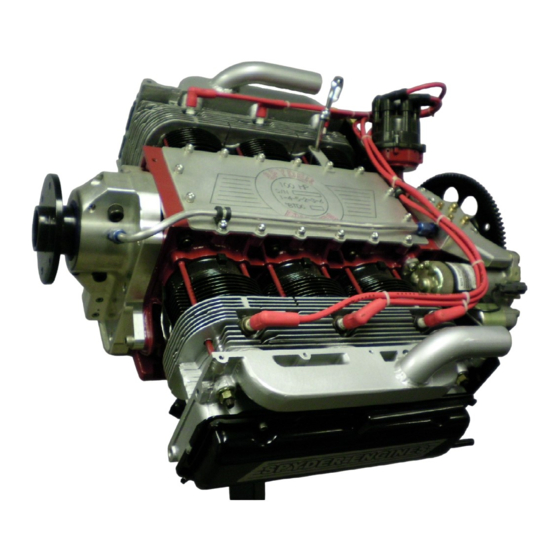
- Page 58 A finish up engine on display – wires are cleanly routed and tied Section 12 - 4 Azalea Aviation LLC, Copyright 2014...
-
Page 59: Final Details
The rear of the engine will require cooling baffles that will tie into either the plenums or standard baffle kit. These are available through Azalea Aviation or could be fabricated by the engine owner. Our production engine come with them installed. - Page 60 Once every couple of months, remove the plugs, spray a bit of WD40 in each cylinder and turn the engine over a couple times. A bit of research on other ways to improve storage will help as well. Section 13 - 2 Azalea Aviation LLC, Copyright 2014...
-
Page 61: Conclusion
We here at Azalea Aviation are please with the Spyder Engine products that we are producing and hope we have lived up to your expectation. If there is any way that we can help you as a builder during the next phases please let us know. -
Page 62: Specifications And Torque Charts
Forged Std + .040 Oversize Rings Hastings Chrome rings +.040 Bearings Clevite Camshaft LS1 / OT10 Lifters Hydraulic Sealed Power Valves and grind Stainless and three angle grind Springs New Stock Section 15 - 1 Azalea Aviation LLC, Copyright 2014... - Page 63 For all tolerances required for an engine rebuild please refer to our Engine Disassembly and Conversion Manual. Most pertinent data if needed is also available in a Corvair Chassis Shop Manual. Section 15 - 2 Azalea Aviation LLC, Copyright 2014...
- Page 64 SPYDER ENGINE ASSEMBLY CHECKLIST SHEET Date: _____________________________ Customer:___________________________ S.N. ______________________ COLOR: __________________ MODEL: ____________________ CHECK DESCRIPTION INSTALLED NOTES SHORTBLOCK IFB CASE - Cleaned and Prepped SN ____________________________ IFB Crankshaft Mains __________ Rods___________ Camshaft Model __________________________ Main Bearings Size and make ___________________ Galley Plugs Installed IFB Bearings Size ____________________________...
- Page 65 Heads Installed Pushrod tubes Installed Head Torqued Valve Train Installed and Adjusted Valve Covers Installed Oil Pickup Installed and Bolt torqued Oil Pan Installed and torqued Dipstick Installed FINAL Oil Lines and filter Installed Engine Pre-oiled Top Cover Installed and Torqued Distributor Installed and Adjusted Exhaust Intake...
Need help?
Do you have a question about the SPYDER 100 HP and is the answer not in the manual?
Questions and answers