Advertisement
Quick Links
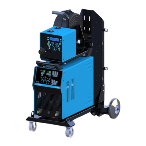
iMIG 400S
SYNERGIC MIG WELDING MACHINE
SAFETY DEPENDS ON YOU
Colton arc welding equipments are designed and built with safety in mind. However proper
installation and operation on your part can increase your overall safety. DO NOT INSTALL,
OPERATE OR REPAIR THIS EQUIPMENT WITHOUT READING THIS OPERATING MANUAL
AND THE SAFETY PRECAUTIONS CONTAINED THROUGHOUT.
OPERATOR'S MANUAL
COLTON WELDTEK PVT LTD
BANGALORE
Advertisement

Summary of Contents for Colton Weldtek iMIG 400S
- Page 1 Colton arc welding equipments are designed and built with safety in mind. However proper installation and operation on your part can increase your overall safety. DO NOT INSTALL, OPERATE OR REPAIR THIS EQUIPMENT WITHOUT READING THIS OPERATING MANUAL AND THE SAFETY PRECAUTIONS CONTAINED THROUGHOUT. OPERATOR’S MANUAL COLTON WELDTEK PVT LTD BANGALORE...
- Page 2 Safety precautions ARC WELDING CAN BE HAZARDOUS. PROTECT YOURSELF AND OTHERS FROM POSSIBLE SERIOUS INJURY OR DEATH. KEEP CHILDREN AWAY. PACEMAKER WEARERS SHOULD CONSULT WITH THEIR DOCTOR BEFORE OPERATING. BE SURE THAT ONLY QUALIFIED INDIVIDUALS PERFORM ALL INSTALLATION, OPERATION, MAINTENANCE AND REPAIR PROCEDURES For Engine Powered equipments 1.a.
- Page 3 ELECTRIC AND MAGNETIC FIELDS may be dangerous 2.a. Electric current flowing through any conductor causes localized Electric and Magnetic Fields (EMF). Welding current creates EMF fields around welding cables and welding machines. 2.b. EMF fields may interfere with some pacemakers, and welders having a pacemaker should consult their physician before welding.
- Page 4 Semiautomatic DC Constant Voltage (Wire) Welder DC Manual (Stick) Welder AC Welder with Reduced voltage control 3.c. In semiautomatic or automatic wire welding, the electrode, electrode reel, welding head, nozzle or semiautomatic welding gun are also electrically “hot”. 3.d. Always be sure the work cable makes a good electrical connection with the metal being welded. The connection should be as close as possible to the area being welded.
- Page 5 FUMES AND GASES can be dangerous 5.a. Welding may produce fumes and gases hazardous to health. Avoid breathing these fumes and gases. When welding, keep your head out of the fume. Use enough ventilation and/or exhaust at the arc to keep fumes and gases away from the breathing zone. When welding with electrodes which require special ventilation such as stainless or hard facing (see instructions on container or MSDS) or on lead or cadmium and plated steel and other materials or coatings which produce highly toxic fumes, keep exposure as low as possible and below Threshold Limit Values (TLV) using...
- Page 6 WELDING AND CUTTING SPARKS can cause fire or explosion. 6.a. Remove fire hazardous from the welding area. If this is not possible, cover them to prevent the welding sparks from starting a fire. Remember that welding sparks and hot materials from welding can easily go through small cracks and openings to adjacent areas.
- Page 7 CYLINDER may explode if damaged. 7.a. Use only compressed gas cylinders containing the correct shielding gas for the process used and properly operating regulators designed for the gas and pressure used. All hoses, fittings, etc. should be suitable for the application and maintained in good condition. 7.b.
- Page 8 Principle & Technical data iMIG series welding machine Block diagram Power supply Rectifier Main Rectifier inverter transformer &Filter Control circuit Block diagram of principle This series welding machines applies IGBT soft switch inverter technology. 3- phase power supply is rectified, inverted into high frequency AC using soft switch technology, transformed into low voltage using HF transformer, rectified and filtered by fast recovery diodes &...
- Page 9 1. Main technical parameters iMIG 400S iMIG 500S Model Three phase Three phase Rated input voltage (V) 415V±10%/50Hz 415V±10%/50Hz Rated input power (KVA) @100% Rated input current (A) Rated output voltage(V) Open circuit voltage (V) Range of welding voltage (V)
- Page 10 2. Components list Items iMIG 400S iMIG 500S Circuit Breaker Rectifier 3-phase EMI Filter coil PCB EMI filter Capacitor DC link C1 IGBT module Capacitor C2-C5 Inductor input L1 Capacitor snubber IGBT C6 Diode Fast Recovery PCB IGBT protection PCB Current sensor...
- Page 11 PCB IGBT soft drive Connectror J-2/1 Circuit breaker 6A Fuse 2A Thermostat TH-1 PCB iMIG control PCB iMIG display...
- Page 12 Features & Applications iMIG series inverter CO /MIG welders are high-quality performers that can be used for semi-automatic gas shield welding with solid or flux-cored wire (Ф0.8-Ф1.6mm) for welding mild steel and low alloy steel work apart from MMAW. This series welder enjoys excellent static characteristic and sound dynamic characteristic.
- Page 13 Installation Guide 1. Pre-installation 1.1 Installation Environment iMIG series welding machine are designed for use in adverse environments. Examples of environments with increased adverse conditions are: Locations in which freedom of movement is restricted, so that the operator is forced to perform the work in a cramped (kneeling, sitting or lying) position with physical contact with conductive parts;...
- Page 14 1.4.Power Supplier Requirements Input volt must be standard sine wave, effective value 400V±10%, frequency 50Hz. Unbalance degree of 3- phase volt must be no more than 5% iMIG 400S iMIG 500S Model Power supply 415V / 3phase 415V / 3phase...
- Page 15 Ensure the welder is placed at a even location. The outside connection of the welder is shown in figure 5: Outside Connection Diagram 4.1 Preparation prior to operation procedure: Connect the welder’s terminal plug (-) to work piece. Connect the welder’s terminal plug (+) to wire feeder by welding cable. Connect the welder’s control cable socket to wire feeder by control cable.
- Page 16 unplug the power cord while not welding. Welding current(A) Welding voltage(V) Suitable wire(mm) Ф0.8、Ф1.0 60-80 17-18 Ф1.0、Ф1.2 80-130 18-21 Ф1.0、Ф1.2 130-200 20-24 Ф1.0、Ф1.2 200-250 24-27 Ф1.2、Ф1.6 250-350 26-32 Suggested voltage and Ampere for different wire size It is better to choose torch in accordance with EN60974-12 Please refer to appendix B for EMC suggestions for installation and use of welder.
- Page 17 Operating Instruction 1. Panel illustration 1.1 Quick plug socket for welding cable (-) Connect to workpiece through output cable. 1.2 Control socket The control socket is a 7 pin MS-style connector to communicate between the power source & the wire feeder. Connect the control cable. 1.1 Control panel The control panel is used for functional selection and setting some welding parameters.
- Page 18 1.3.1 Functional selection 1.3.1.1 Wire diameter selection key Selecting wire diameter among Φ1.6, Φ1.2, Φ1.0 & 0.8mm, and the related LED will light on. 1.3.1.2 “Individual/Synergic” selection key Select individual/synergic mode. On “Individual” mode, welding current and voltage can be adjusted individually by regulating controller of wire feeder.
- Page 19 1.3.1.4 “Wire Inch” key The wire feeds when pressing on the key and the related LED will light on. Stop feeding by releasing the key. (It has the same function as to press the inching button on the wire feeder controller) 1.3.1.5 PROCESS selection key Selecting the different processes “MMAW/GMAW (NORMAL-SYNERGIC)/ GMAW (ROOT WELD)/ GMAW (FORCE ARC)”and the related LED will light on.
- Page 20 (3) Advanced 4-step: This mode provides additional features to the normal 4-step where start weld & end weld features is incorporated. (4)Arc spot welding: After successfully starting arc by push torch trigger, the welder will stop welding automatically at the end of arc spot welding time. If release the trigger during arc spot welding, the welder will stop welding immediately.
- Page 21 1.3.1.9 Control / Store / Settings display (1) An indicator lamp will light on when displaying Remote. In this setting, the controls for voltage & wire feed speed can be set from the wire feeder or any external location. The machine panel encoders are inactive.
- Page 22 PROGRAM DESCRIPTION RANGE DEFAULT UNIT Pre Gas time 0.0 - 3.0 Sec. Post Gas time 0.0 - 5.0 Sec. Burn back time 0.0 - 3.0 Sec. Burn back voltage 10.0 - 14.0 Show wire feed speed 03 - 10 Wire feeder Internal/External 0 / 1 Max.
- Page 23 1.3.3.2 Current display Display welding current, arc spot welding time & trigger activation. (1) “A” indicator lamp will light on when displaying welding current. It displays preset current during no load, and actual value during welding. (2) While in “Arc spot welding time”, adjusts arc spot welding time from 0.5 to 5 seconds. 1.3.3.3 Voltage display It displays Stick out, Volt, Inductance &...
- Page 24 Input power cable The mixed-colored wire must be firmly grounded, the rest wires are connected to 3-phase power (415V±10%/50Hz) respectively. Circuit breaker The function of circuit breaker is to protect welding machine by automatic trip to turn-off power supply while overload or failure. ...
- Page 25 Repair & Maintenance WARNING: Have a qualified electrician do the maintenance and trouble shooting work. Turn the input power off, using the disconnect switch at the fuse box before working inside the machine. 1. Cautions: Possibilities of damage. Connect welding cable to terminals firmly, otherwise the terminals will be burn out which will cause the instability of welding process.
- Page 26 Clean and replace Contact Tip in time. 3. Procedure for regular checking prior to maintenance Check if all front panel switches are on the proper positions. Check if the input volt has the phase missing, and range are between 360~440V. ...
-
Page 27: Troubleshooting Table
№ TROUBLE REASON WHAT TO DO (1)Phase missing (1)Check power supply Indicator lamp does not light on (2)Circuit breaker is damaged (2)Replace when machine switches on. (3)Fuse is broken (3)Replace fuse (2A) (1)Replace (1)Circuit breaker is collapsed. (2)Replace IGBT module (2)IGBT module is damaged. - Page 28 Appendix A 1. General The user is responsible for installing and using the arc welding equipment according to the manufacturer’s instructions. If electromagnetic disturbances are detected, then it shall be the responsibility of the user of the arc welding equipment to resolve the situation with the technical assistance of the manufacturer.
- Page 29 3. Methods of reducing emissions 1) Public supply system Arc welding equipment should be connected to the public supply system according to the manufacturer’s recommendations. If interference occurs, it may be necessary to take additional precautions such as filtering of the public supply system. Consideration should be given to shielding the supply cable of permanently installed arc welding equipment, in metallic conduit or equivalent.
- Page 30 5) Earthling of the work piece Where the work piece is nor bonded to earth for electrical safety, nor connected to earth because of its size and position, for example ships hull or building steelwork, a connection bonding the work piece to earth may reduce emissions in some, but not all instances. Care should be taken to prevent the earthling of the work piece increasing the risk of injury to users, or damage to other electrical equipment.
- Page 31 Circuit diagram...
- Page 32 COLTON WELDTEK PVT LTD BANGALORE TEST CERTIFICATE INVERTER IGBT MIG WELDING MACHINE MODEL No: iMIG 400S SERIAL No: INPUT VOLTAGE 415 VOLT, 3Ph, 50Hz COOLING FORCED AIR INSULATION RESISTANCE TEST NO LOAD TEST LOAD TEST ELECTRICAL SPECIFICATIONS Open circuit voltage...
Need help?
Do you have a question about the iMIG 400S and is the answer not in the manual?
Questions and answers