Advertisement
Quick Links
BENJOLIN V2 MANUAL
Manual Revision B
HISTORY
The Benjolin is originally a 'patch in a box', meaning a couple of
'modules' patched up in a fixed way and put in a box to create a
specific kind of standalone instrument. This patch is not intended to
create music based on melodies, harmonies and specific rhythms, but to
create 'sound scapes' of pure electronic sounds. Meaning it's an
'electronic music instrument', an instrument to create electronic
music in its most pure and abstract forms.
The first version of the Benjolin was designed as a kit in the year
2009, for the purpose to organize DIY workshops where people could
build a Benjolin themselves. Every participant was taken by the hand
to successfully build one, even if they had never built a piece of
electronics before and/or used a soldering iron. A necessary
requirement for the design was to keep it simple, it should not take
more as about four hours for a complete novice to build a kit. And so
the first Benjolin was fully based on the punk principle of 'the
minimum for the maximum'.
Hundreds of people all over the world have built Benjolins in these
workshops and virtually everyone succeeded in finishing and go home
with a properly working Benjolin. At this time the technique of
circuit bending was popular, and the name Benjolin originates as 'an
electronic crossover between a banjo and a violin' that is 'bent by
design'. The banjo being an instrument associated with popular music
and the violin being associated with a bit elite music, and the
built-in crazy behavior associated with circuit bending. So, an
instrument for everybody, to give incredible fun while exploring its
behavior. As a standalone instrument this DIY Benjolin was a good
companion for guitar stompboxes and other effects units, with line
level audio inputs.
Soon it became clear that the Benjolin was actually very useful in
creating pure and abstract electronic music. The kind of music that
the designer of the Benjolin thinks began with e.g. the soundtrack of
the movie Forbidden Planet around the year 1956. Several composers and
Advertisement

Summary of Contents for After Later Audio BENJOLIN V2
- Page 1 BENJOLIN V2 MANUAL Manual Revision B HISTORY The Benjolin is originally a ‘patch in a box’, meaning a couple of ‘modules’ patched up in a fixed way and put in a box to create a specific kind of standalone instrument. This patch is not intended to create music based on melodies, harmonies and specific rhythms, but to create ‘sound scapes’...
- Page 2 It’s now well over ten years after the first Benjolin workshops, and some time ago the Epoch version disappeared from the market. This made After Later Audio and Rob Hordijk decide to join hands, and that now was the time to make a new design specifically for Eurorack with many more features brought to the outside of the module and inputs and outputs properly specified to be used in a Eurorack setup.
- Page 3 It should help you get a feel for how to control this complicated chaos machine. New to the Benjolin V2: Reworked oscillator and filter sections All levels are adjusted to Eurorack standards Two different steps modes (8/16 and 127) ...
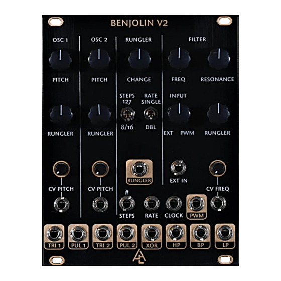
- Page 4 OSCILLATORS Oscillator 1 and 2 have identical controls and inputs/outputs. Pitch: Coarse pitch control to control the frequency of each oscillator. Rungler: The ammount of Rungler stepped CV that is applied to each oscillator. CV Pitch: CV pitch input with an attenuator to control the amount of impact on the pitch of the oscillator.
- Page 5 RUNGLER The Rungler section is centered on a shift register that uses an R2R DAC to create a stepped CV voltage. There are two inputs into the shift register, the data to sample (which comes from OSC1) and clock speed (which comes from OSC2).
- Page 6 Rungler: The actual stepped CV output that ranges from -5V to +5V. Steps/Rate CV Inputs: The switches are configured so that when the switch is up you will get the same behavior as passing a high voltage. XOR: The output of one bit from the shift register resulting in a random gate output.
- Page 7 MIXER Controls the input into the filter section. PWM: The output of the comparator of the triangle wave from OSC1 and OSC2 resulting in a square wave with variable width. Ext In: An external audio input Input: Controls the blend between PWM and Ext In that is fed to the filter input.
- Page 8 FILTER Freq: Controls the cutoff frequency of the multimode filter Resonance: Controls the resonance of the multimode filter. Delivers more wetness than a Seattle winter. Rungler: The amount of Rungler stepped CV that is applied to cutoff frequency. CV Freq: CV pitch input with an attenuator to control the amount of impact on the cutoff frequency.
-
Page 9: Signal Flow
SIGNAL FLOW... - Page 10 GETTING MORE INTIMATE WITH YOU BENJOLIN Undoubtedly you have already tried out the Benjolin V2 before reading the manual or this text. Most probably you got lots of totally crazy sounds and undoubtedly have wondered if it is at all possible to get any kind of control over the sounds.
-
Page 11: Check It Out
‘symmetry’ between the two vcos, each could e.g. go to a left and a right audio channel on a mixer, and then you can apply crossmodulation between the two vcos. This would give you two related drone signals, each on its own channel. The total range of the vco pitch knob is from one cycle every 45 seconds at the ccw position to about 8kHz at the cw position. - Page 12 detuning and second you hear the character of the sound change from the typical ‘hollow’ triangle wave to a much more bright sawtooth wave. This effect may not be very spectacular yet, but when the vco is used at lfo rates changing the waveshape this way can produce nice results. NORMALIZATION If there is no jack connected to a cv pitch mini-jack connector on a vco then the mini-jack connector is normalized to the trianglewave...
- Page 13 Now you should think of every possible combination of patching only the four osc outputs and two osc inputs, while listening directly to one or more of the four outputs. Both selfmodulation and crossmodulation are possible, and all create their own specific effects.
- Page 14 mathematics from frequency modulation formulas into statistic functions. But such circuitry is not present in the Benjolin, and so you need to remember that low pitches easily modulate high pitches but high pitches hardly modulate low pitches at all. Still, later we will see that the rungler is actually behaving like how a S&H would behave and that when using the rungler outputs the modulation mathematics follow the statistic functions and not per se e.g.
- Page 15 The vcf is a more or less ‘standard’ voltage controlled 12dB state- variable filter. It has a single knob ‘equal loudness’ crossfade mixer on its input to allow easy selection of either the internal pwm sound or a sound that comes in at the ext in mini-jack connector. If there is no jack inserted in this connector the crossfade mixer knob can be used as a volume control, ccw is silent and cw sends the internal pwm mixer sound signal to the filter.
- Page 16 crossfade mixer knob fully left and set the resonance knob to a 12 o’clock position. When opening the resonance knob further in the cw direction will start clipping the tops of the sinewave cycles. You can hear the sinewave on both the lp and the hp outputs. By using an external multiple you can also split the bp signal and listen to the bp signal while feeding it back to cause the oscillation.
- Page 17 THE RUNGLER The rungler circuit is based on a binary device named a shift register. This shift register is a cascaded group of one-bit memory cells (D-type flip-flops), all sharing the same ‘write’ clock pulse. On clocking each memory cell passes its stored value of either a one or a zero to the next memory cell and takes over the value of the previous memory cell.
- Page 18 The Benjolin v2 rungler uses three bits for the DA converter, which can produce eight voltage levels at roughly -4V, -3V, -2V, -1V, 0V, +1V, +2V and +3V.
- Page 19 as a rungler circuit would produce sequences of either eight or sixteen steps. But the pattern would be constantly changing at a certain rate, or be frozen in a loop. The relatively short patterns are much more useful musically compared to the longer pseudo-random sequence of a digital noise generator where patterns sound to go nowhere.
- Page 20 flanks in the waveforms the filter should have good ‘ping’ characteristics, so the flanks can create filter pings when the vcos are at slow rates. The behaviour of the Benjolin is defined by how the rungler output signals are used to modulate the pitches of the vcos and the cutoff of the vcf.
- Page 21 Also modulating the vcf at this range with a high resonance setting can create very nice results. In the Benjolin V2 there are additions and expansions to the rungler circuit that were not present in the original diy-version of the Benjolin.
- Page 22 the sawtooth, but if a upsloping sawtooth wave or a triangle wave is used the clocking seems to be slightly delayed. Because it takes a short while before the upgoing slope has reached the toggle point. Frontpanel connector outputs are all in the +5V<>-5V Eurorack range. Additionally you can use the pul1, pul2, xor and pwm outputs to directly clock e.g.
- Page 23 EXPANSION HEADERS TURING MACHINE EXPANDER SUPPORT Thanks to Tom Whitwell for making this possible...
- Page 24 MORE CONTENT Rob Hordijk’s blog post that explains the Rungler Video of Rob Hordijk explaining the Rungler.
Need help?
Do you have a question about the BENJOLIN V2 and is the answer not in the manual?
Questions and answers