Table of Contents
Advertisement
Quick Links
Advertisement
Table of Contents

Summary of Contents for ARCOMA PRECISION i5
- Page 1 Operation Manual ARCOMA PRECISION i5 Doc.No.: 1000-095-051-EN Rev. 1.1...
- Page 2 ARCOMA PRECISION i5 INTENDED USE The System is a stationary X-ray system intended for obtaining radiographic images of various portions of the human body in a clinical environment. The System is not intended for mammography. CAUTION: US Federal Law restricts this device to sale by or on order of a physician.
- Page 3 Revision Revision history Update Chapter/ Date Pages New Release 2020-06 Operation Manual 1000-095-051-EN Rev. 1.1 ARCOMA AB 2020-06-16 SWEDEN...
- Page 4 Revision Operation Manual ARCOMA AB 1000-095-051-EN Rev. 1.1 SWEDEN 2020-06-16...
-
Page 5: Table Of Contents
Introduction ....................1 Document information ..................1 1.1.1 System documentation ................1 1.1.2 Stylistic conventions ................1 1.1.3 Document producer.................1 1.1.4 Copyright © 2020 Arcoma Corporation all rights reserved......1 1.1.5 Text emphasis..................1 Identification Labels ..................3 System Description ..................6 1.3.1 General ....................6 1.3.2 Intended Use ..................6 1.3.3... - Page 6 Basic exposure error handling .............. 103 Movement Short-cut Zones................. 104 4.5.1 Wallstand Short-cut Zone ..............105 4.5.2 Table Short-cut Zone ................105 Transport Interval Zone ................106 Manual Mode .................... 107 Operation Manual ARCOMA AB 1000-095-051-EN Rev. 1.1 SWEDEN Page ii 2020-06-16...
- Page 7 Configuration ..................148 8.2.3 Weight....................148 8.2.4 Electrical Characteristics ..............148 8.2.5 Classification ..................148 8.2.6 Speed ....................149 Cabinet ..................... 150 8.3.1 Dimensions ..................150 8.3.2 Weight....................150 Operation Manual 1000-095-051-EN Rev. 1.1 ARCOMA AB 2020-06-16 Page iii SWEDEN...
- Page 8 10.1.4 Grid....................156 11 Appendix A....................157 11.1 Glossary ....................157 12 Appendix B....................161 12.1 Monthly Checklist..................161 12.1.1 OTC....................161 12.1.2 Remark ....................164 12.2 Annual Checks ..................165 Operation Manual ARCOMA AB 1000-095-051-EN Rev. 1.1 SWEDEN Page iv 2020-06-16...
-
Page 9: Introduction
• The original version of this manual is written in English. • Training is provided by or via Arcoma. Training material consists of the Operation manual and the Installation and service manual. - Page 10 Note! All texts labelled with “NOTE” contain additional information regarding the work step, and is provided for a better understanding or as a warning about unnecessary and avoidable difficulties. Operation Manual ARCOMA AB 1000-095-051-EN Rev. 1.1 SWEDEN Page 2 2020-06-16...
-
Page 11: Identification Labels
Introduction Identification Labels 1.2 Identification Labels The figure shows the location of the identification labels on the equipment. 1000 Fig. 1-1 Operation Manual 1000-095-051-EN Rev. 1.1 ARCOMA AB 2020-06-16 Page 3 SWEDEN... - Page 12 Introduction Identification Labels Operation Manual ARCOMA AB 1000-095-051-EN Rev. 1.1 SWEDEN Page 4 2020-06-16...
- Page 13 Introduction Identification Labels 1000 1000 Operation Manual 1000-095-051-EN Rev. 1.1 ARCOMA AB 2020-06-16 Page 5 SWEDEN...
-
Page 14: System Description
Introduction System Description 1.3 System Description 1.3.1 General Arcoma Precision includes: • Overhead tube crane (OTC) with x-ray tube and collimator • Table • Wall stand • System cabinet with a high voltage generator • Image Acquisition system • Flat panel detectors 1.3.2 Intended Use... -
Page 15: System Overview
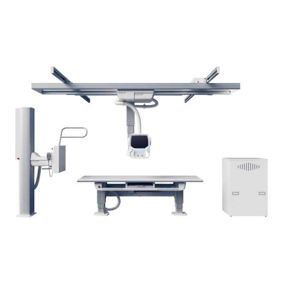
System Description 1.3.4 System Overview Fig. 1-2 System Overview 1. Overhead tube crane, OTC 2. Table 3. Detector holder 4. Wall stand 5. System cabinet 6. Computer and monitor Operation Manual 1000-095-051-EN Rev. 1.1 ARCOMA AB 2020-06-16 Page 7 SWEDEN... -
Page 16: Overhead Tube Crane, Overview
Fig. 1-3 Overhead Tube Crane, OTC 1. Ceiling rail (Y) 5. X-ray tube 2. Traverse rail (X) 6. Manoeuvre handle 3. Ceiling wagon 7. Collimator 4. Column (Z) 8. Display Operation Manual ARCOMA AB 1000-095-051-EN Rev. 1.1 SWEDEN Page 8 2020-06-16... - Page 17 9. Collimator hand control (option) 4. Table hand control (X/Y/Z, Ceiling tube pendulum movement) 10. Head end 5. Detector holder 11. Foot end 6. Brake release for detector holder Operation Manual 1000-095-051-EN Rev. 1.1 ARCOMA AB 2020-06-16 Page 9 SWEDEN...
-
Page 18: Wall Stand Overview
1.3.7 Wall stand Overview Fig. 1-5 Wall stand overview, T = Tilt 1. Lateral armrest 5. Hand control (Collimator and movement 2. Detector holder adjustments) 3. Column 4. Foot plate Operation Manual ARCOMA AB 1000-095-051-EN Rev. 1.1 SWEDEN Page 10 2020-06-16... -
Page 19: Safety
Safety Modification of equipment 2 Safety 2.1 Modification of equipment WARNING! No modification of this equipment is allowed. Operation Manual 1000-095-051-EN Rev. 1.1 ARCOMA AB 2020-06-16 Page 11 SWEDEN... -
Page 20: Compliance
In particular such a Separation Device is required when a network connection is made. The requirements on the Separation Device is defined in IEC 60601–1–1 and in IEC 60601–1, edition 3, clause 16. Operation Manual ARCOMA AB 1000-095-051-EN Rev. 1.1 SWEDEN Page 12... -
Page 21: Qualifications Of Personnel
Note! It is the responsibility of the owner to ensure that the product is operated only by trained radi- ologist, service technicians or product specialists. Operation Manual 1000-095-051-EN Rev. 1.1 ARCOMA AB 2020-06-16 Page 13 SWEDEN... -
Page 22: Service And Maintenance
Risk of electric shock to patient or user • No non-medical electrical devices shall be used in the x-ray room. • Note that the monitor and the PC for the Image system, are none-medical approved products. Operation Manual ARCOMA AB 1000-095-051-EN Rev. 1.1 SWEDEN Page 14 2020-06-16... - Page 23 Only service engineers are allowed to open the covers. CAUTION! When installing this equipment in a different location, contact us or our designated dealer. CAUTION! Do not remove, disassemble, change, modify, repair, or add any part. Operation Manual 1000-095-051-EN Rev. 1.1 ARCOMA AB 2020-06-16 Page 15 SWEDEN...
-
Page 24: Safety And Warning Symbols
Manufacture date producer To indicate the emission or the imminent emission of X-radiation. Marking on the emergency stop button. Activation of the actuator in- terrupts all mechanical movements and prohibits exposures. Operation Manual ARCOMA AB 1000-095-051-EN Rev. 1.1 SWEDEN Page 16 2020-06-16... -
Page 25: Safety And Warning Labels On The Equipment
25 kg = 55 lbs Max 25 kg 25 kg = 55 lbs Max 25 kg 300 kg = 661 lbs Max 300 kg Fig. 2-1 Locations of safety and warning labels Operation Manual 1000-095-051-EN Rev. 1.1 ARCOMA AB 2020-06-16 Page 17 SWEDEN... -
Page 26: Emergency Stop
There are additional external emergency stops as option. Fig. 2-2 Emergency stop buttons Operation Manual ARCOMA AB 1000-095-051-EN Rev. 1.1 SWEDEN Page 18 2020-06-16... -
Page 27: Radiation And X-Ray Tube
CAUTION! To minimize the x-ray dose: - keep the distance between the focal spot and patient as large as possible. - and the beam size as small as possible. Operation Manual 1000-095-051-EN Rev. 1.1 ARCOMA AB 2020-06-16 Page 19 SWEDEN... -
Page 28: Mechanical Safety
Surrounding equipment are not subject of the collision warning. 2.9.1 General It is the operators duty, before any movements are activated, to ensure that any danger to the patient and/or third person is prevented. Operation Manual ARCOMA AB 1000-095-051-EN Rev. 1.1 SWEDEN Page 20 2020-06-16... -
Page 29: Overhead Tube Crane
• column (1) and the column bottom plate (4) when the column is moving upwards (Z- direction). • cover (2) and the column (1) when the X-ray tube is moving in Beta (β) direction Operation Manual 1000-095-051-EN Rev. 1.1 ARCOMA AB 2020-06-16 Page 21 SWEDEN... -
Page 30: Table
3. Column cover foot 7. Column (Z) 4. Imaging unit (X) 8. Footplate WARNING! Squeezing hazards may occur between the table top and the imaging unit or the imag- ing unit rail. Operation Manual ARCOMA AB 1000-095-051-EN Rev. 1.1 SWEDEN Page 22 2020-06-16... - Page 31 (1). Power loss will also release the brakes enabling moving the detector holder. The brake is normally activated, at power loss the brake is released. Fig. 2-5 1. Detector holder 2. Manoeuver control Operation Manual 1000-095-051-EN Rev. 1.1 ARCOMA AB 2020-06-16 Page 23 SWEDEN...
-
Page 32: Wallstand
• The maximum weight to put on the Wallstand lateral armrest is restricted to 25 kg. • For the Wallstand detector holder the maximum weight is set to 10 kg. Operation Manual ARCOMA AB 1000-095-051-EN Rev. 1.1 SWEDEN Page 24... -
Page 33: Safety Issues When Placing The Patient
Due to squeezing hazards, patients shall always have their extremities placed over the table top. CAUTION! When the table top switch is activated, the table top will be floating, therefore do not lean against the table top Operation Manual 1000-095-051-EN Rev. 1.1 ARCOMA AB 2020-06-16 Page 25 SWEDEN... - Page 34 The operator should then drag the mattress with the patient from the hospital bed to the X-ray Table. 002276_0072.epss Fig. 2-7 Placement of the table top when loading the patient. Operation Manual ARCOMA AB 1000-095-051-EN Rev. 1.1 SWEDEN Page 26 2020-06-16...
-
Page 35: Working Area
The measurements in Fig. 2-8 show the length of the stroke in the X- and Y-direction. Fig. 2-8 The Fig. 2-9 shows the dimensions underneath the table Fig. 2-9 Operation Manual 1000-095-051-EN Rev. 1.1 ARCOMA AB 2020-06-16 Page 27 SWEDEN... -
Page 36: Weight Restrictions, Table
Fig. 2-12 Maximum patient weight label The table frame is marked on the upper side with the maximum weight when positioning in outer positions, see Fig. 2-12 Maximum patient weight label. Operation Manual ARCOMA AB 1000-095-051-EN Rev. 1.1 SWEDEN Page 28... -
Page 37: Safety Functions
• Two sensors registering objects close to the handles on detector holder. If an object is reg- istered the movement stops and cannot continue until the object is removed. Operation Manual 1000-095-051-EN Rev. 1.1 ARCOMA AB 2020-06-16 Page 29 SWEDEN... -
Page 38: Collision Detection
The System will take this as a sign that the operator has re- moved the obstacle and that no collision exists any more. If the problem is yet not solved, the System must be restarted. Operation Manual ARCOMA AB 1000-095-051-EN Rev. 1.1 SWEDEN Page 30... -
Page 39: Quick Abortion Of An Auto Positioning
All movements require constant activation of the chosen button. If the operator releases one of the buttons/controls, the system will immediately stop or en- gage the brakes (manual movements). The exposure operator console has the same functionality. Operation Manual 1000-095-051-EN Rev. 1.1 ARCOMA AB 2020-06-16 Page 31 SWEDEN... -
Page 40: Electromagnetic Compatibility (Emc)
Do not place the system near MRI equipment or other equipment that generates a strong magnetic field. CAUTION! Mobile telephones and other radiating equipment can interfere with the function of the system and can therefore cause safety hazards. Operation Manual ARCOMA AB 1000-095-051-EN Rev. 1.1 SWEDEN Page 32 2020-06-16... - Page 41 Voltage fluctuations/ Flick- Not applicable IEC61000-3-11 and is suitable for connection to pub- er emissions IEC 61000-3- lic mains network if the impedance is 0.32 Ohm or lower Operation Manual 1000-095-051-EN Rev. 1.1 ARCOMA AB 2020-06-16 Page 33 SWEDEN...
- Page 42 (LV) overhead power lines. 20 dB relaxation for Quasi- Peak (QP) is allowed for Radiography and pulsed Radiography (Intermittent Mode). Operation Manual ARCOMA AB 1000-095-051-EN Rev. 1.1 SWEDEN Page 34 2020-06-16...
- Page 43 30 A/m Power frequency magnetic fields should (50/60 Hz) mag- be at levels characteristic of a typical loca- netic field tion in a typical commercial or hospital environment. IEC 61000-4-8 Operation Manual 1000-095-051-EN Rev. 1.1 ARCOMA AB 2020-06-16 Page 35 SWEDEN...
- Page 44 NOTE 1: These guidelines may not apply in all situations. Electromagnetic propagation is affected by absorption and reflection from structures, objects and people. Operation Manual ARCOMA AB 1000-095-051-EN Rev. 1.1 SWEDEN Page 36 2020-06-16...
- Page 45 (W) according to the transmitter manufacturer. NOTE 1: These guidelines may not apply in all situations. Electromagnetic propagation is affected by absorption as reflection from structures, objects and people. Operation Manual 1000-095-051-EN Rev. 1.1 ARCOMA AB 2020-06-16 Page 37 SWEDEN...
- Page 46 Safety Electromagnetic compatibility (EMC) Operation Manual ARCOMA AB 1000-095-051-EN Rev. 1.1 SWEDEN Page 38 2020-06-16...
-
Page 47: User Interface
The figure below shows the movements of the OTC. Alpha Beta Fig. 3-1 OTC direction of movement Vertical movement Motorized Lateral movement Motorized and manual Longitudinal movement Motorized and manual Operation Manual 1000-095-051-EN Rev. 1.1 ARCOMA AB 2020-06-16 Page 39 SWEDEN... -
Page 48: Sound Signal
• Two sound signals, in rapid succession, indicates a fault and the display will show an error message, for example after a collision. The error message shows the corrective action. Operation Manual ARCOMA AB 1000-095-051-EN Rev. 1.1 SWEDEN Page 40... -
Page 49: System Display Overview
8. Light indication, see 3.2.15 Light 3. Y direction indication 4. X direction 9. Display user interface, see 3.2.2 5. Emergency brake (rear side) Display user interface 6. Release all directions (rear side) Operation Manual 1000-095-051-EN Rev. 1.1 ARCOMA AB 2020-06-16 Page 41 SWEDEN... -
Page 50: Automatic Collimator Control
4. Measuring tape grip for SID measurement, graduation in cm/inch - Take reading at bottom edge of multi-leaf collimator. 5. Accessory rail The collimator can rotate around the central beam axis +/-90°. Operation Manual ARCOMA AB 1000-095-051-EN Rev. 1.1 SWEDEN Page 42 2020-06-16... -
Page 51: Automatic Collimator
(for the same patient) the collimator light / x-ray field size or the filtration is not changed even if size and filtration is defined different in the protocol. Operation Manual 1000-095-051-EN Rev. 1.1 ARCOMA AB 2020-06-16 Page 43 SWEDEN... - Page 52 In Free mode/Auto position mode the position of the detector is unknown for the System. The indicated size of the light field is correct at the shown SID. Operation Manual ARCOMA AB 1000-095-051-EN Rev. 1.1 SWEDEN Page 44...
- Page 53 F. Button for closing the format width collimation. 3.2.1.7 Hand control, Wall stand – collimator adjustment A. Collimator light on/off B. Adjustment height collimation C. Adjustment width collimation Fig. 3-5 Hand control Operation Manual 1000-095-051-EN Rev. 1.1 ARCOMA AB 2020-06-16 Page 45 SWEDEN...
-
Page 54: Display User Interface
9. Selection of active AEC field (AEC mode only) 10. Patient size 11. Collimator centering 12. Manual or Servo mode 13. Density See the following pages for detailed description of the functions. Operation Manual ARCOMA AB 1000-095-051-EN Rev. 1.1 SWEDEN Page 46 2020-06-16... -
Page 55: Patient Information
The height to floor (H) is shown in Free mode and Auto position mode. In all other modes the source image distance (SID) is shown. The unit for the distance can be either cm or inch, and is set in the Setting menu (Fig. 3-7 Position information). Operation Manual 1000-095-051-EN Rev. 1.1 ARCOMA AB 2020-06-16 Page 47 SWEDEN... -
Page 56: Adjustment Of Generator Parameters (Kv, Ma, Ms, Mas, Density)
The Setting menu has the following tabs; User Settings and Service. User settings has the following tabs: Display, Settings and Themes. Service has the following tabs: Log, Settings and Display. Operation Manual ARCOMA AB 1000-095-051-EN Rev. 1.1 SWEDEN Page 48... - Page 57 When the Always on is not marked, the Pa- tient information is shown when pushing the black field where the ‘i’ is. Fig. 3-12 “Always On” not selected. The Patient information closes automatically. Operation Manual 1000-095-051-EN Rev. 1.1 ARCOMA AB 2020-06-16 Page 49 SWEDEN...
- Page 58 • Date of Birth (DoB), different formats selectable – YYYY-MM-DD – DD-MM-YYYY – MM-DD-YYYY • ID • Age • Sex • Accession number • Examination/Active Protocol Operation Manual ARCOMA AB 1000-095-051-EN Rev. 1.1 SWEDEN Page 50 2020-06-16...
- Page 59 • Localization unit selection • Audio key click, On/Off • System sound, On/Off • LCD brightness, Plus/Minus • Arcoma logotype in display, On/Off – Image preview on By selecting this, a small preview image will be shown next to the Active Protocol name (see figure on page).
- Page 60 ID 987-65-4320 Hand PA Density post mAs Fig. 3-15 Preview image enlarged The arrows appearing in the image are used to pan in the image. Fig. 3-16 Zooming In/Out Operation Manual ARCOMA AB 1000-095-051-EN Rev. 1.1 SWEDEN Page 52 2020-06-16...
- Page 61 User Interface Automatic Collimator Control Themes USER SETTINGS SERVICE DISPLAY SETTINGS THEMES Arcoma Standard Theme Name #6 Theme Name #8 Theme Name #1 Theme Name #7 Theme Name #9 Theme Name #2 Theme Name #4 Theme Name #10 Theme Name #3...
- Page 62 Save setup A, B XX.XX.X XX.XX.X XX.XX.X COLLIMATOR Bucky XX.XX.X Light Intensity XX.XX.X EMD CIO XX.XX.XXX Light Time (0-60 s) EMD XRAY XX.XX.XXX CONNECTED Fig. 3-20 Service – Settings Operation Manual ARCOMA AB 1000-095-051-EN Rev. 1.1 SWEDEN Page 54 2020-06-16...
-
Page 63: System Mode
The distance shown in display for Free mode is the distance to the floor. Exposure Validation Exposure is allowed if the stand is not moving and operating properly (not in an error state). Operation Manual 1000-095-051-EN Rev. 1.1 ARCOMA AB 2020-06-16 Page 55 SWEDEN... - Page 64 The distance (H) shown in display for Auto position mode is the distance to the floor. Exposure Validation Exposure is allowed if the stand is not moving and operating properly (not in an error state). The chosen position must have been reached successfully. Operation Manual ARCOMA AB 1000-095-051-EN Rev. 1.1 SWEDEN Page 56 2020-06-16...
- Page 65 Exposure is allowed if the stand is not moving, operating properly (not in an error state), the X-ray tube is aimed to the center of the detector and the servo button is activated. Operation Manual 1000-095-051-EN Rev. 1.1 ARCOMA AB 2020-06-16 Page 57 SWEDEN...
- Page 66 Exposure is allowed if the stand is not moving, operating properly (not in an error state), the X-ray tube is aimed to the center of the detector and the servo button is activated. Operation Manual ARCOMA AB 1000-095-051-EN Rev. 1.1 SWEDEN...
- Page 67 In order to produce a large image, images are assembled from multiple exposures with a small, spatial overlap. Stitching is possible at both Table and Wallstand. Composite Image Partial Image Partial Image Partial Image Fig. 3-22 Stitching, schematic description Operation Manual 1000-095-051-EN Rev. 1.1 ARCOMA AB 2020-06-16 Page 59 SWEDEN...
-
Page 68: Hospital Manual
The hospital manual is reached by a activating the Hospital manual button for 1 second. The hospital manual is selectable when a method book has been loaded to the display (per- formed by service engineer) Fig. 3-23 Hospital manual button Operation Manual ARCOMA AB 1000-095-051-EN Rev. 1.1 SWEDEN Page 60 2020-06-16... -
Page 69: Selection Of Technique Mode
Density AEC Backup Fig. 3-25 mAs selection button grayed out For more detailed information about the different technique modes, please see Operator’s Manual for Canon single console CXDI NE. Operation Manual 1000-095-051-EN Rev. 1.1 ARCOMA AB 2020-06-16 Page 61 SWEDEN... - Page 70 (2). All activated AEC fields will be shown in the left picture (1). AEC fields are deactivated by selecting them again in the pop-up window (2). Fig. 3-26 AEC field selection Operation Manual ARCOMA AB 1000-095-051-EN Rev. 1.1 SWEDEN Page 62...
-
Page 71: Patient Size
Note! At the stitching procedure, a change of the Patient size for the first included image in the se- quence, will not be kept for the following included images. Operation Manual 1000-095-051-EN Rev. 1.1 ARCOMA AB 2020-06-16 Page 63 SWEDEN... -
Page 72: Collimator Centering
Top centering, and Bottom centering. Select the desired collimator centering. The pop-up window will automatically close shortly after the selection, and the light field will adjust accordingly. 1. Top 2. Center 3. Bottom Fig. 3-29 Collimator centering selection Operation Manual ARCOMA AB 1000-095-051-EN Rev. 1.1 SWEDEN Page 64 2020-06-16... -
Page 73: Servo State Mode
For further information about Manual mode, see corresponding section. Fig. 3-30 Servo state mode 1. Automatic mode 2. Manual mode Operation Manual 1000-095-051-EN Rev. 1.1 ARCOMA AB 2020-06-16 Page 65 SWEDEN... -
Page 74: Grid Status
When a correction of grid status is needed this is indicated with red text in the Canon inter- face, see detailed description in Table 3-1 Grid status Fig. 3-31 Canon NE user interface. Grid data displayed. Fig. 3-32 Canon NE user interface. Grid removed. Operation Manual ARCOMA AB 1000-095-051-EN Rev. 1.1 SWEDEN Page 66 2020-06-16... - Page 75 Pop up window in Canon lp/cm in Canon). Change to the will guide to exchange the correct grid. grid inserted to the re- quested grid according to the protocol. Operation Manual 1000-095-051-EN Rev. 1.1 ARCOMA AB 2020-06-16 Page 67 SWEDEN...
-
Page 76: System Mode
The distance (H) shown in display for Auto position mode is the distance to the floor. Exposure Validation Exposure is allowed if the stand is not moving and operating properly (not in an error state). The chosen position must have been reached successfully. Operation Manual ARCOMA AB 1000-095-051-EN Rev. 1.1 SWEDEN Page 68 2020-06-16... - Page 77 Exposure is allowed if the stand is not moving, operating properly (not in an error state), the X-ray tube is aimed to the center of the detector and the servo button is activated. Operation Manual 1000-095-051-EN Rev. 1.1 ARCOMA AB 2020-06-16 Page 69 SWEDEN...
- Page 78 Exposure is allowed if the stand is not moving, operating properly (not in an error state), the X-ray tube is aimed to the center of the detector and the servo button is activated. Operation Manual ARCOMA AB 1000-095-051-EN Rev. 1.1 SWEDEN...
- Page 79 In order to produce a large image, images are assembled from multiple exposures with a small, spatial overlap. Stitching is possible at both Table and Wallstand. Composite Image Partial Image Partial Image Partial Image Fig. 3-33 Stitching, schematic description Operation Manual 1000-095-051-EN Rev. 1.1 ARCOMA AB 2020-06-16 Page 71 SWEDEN...
- Page 80 The exposure will be blocked and the user needs to activate the start button once more if; a new parameter setting is received, the System is moved out from the start position, a colli- sion when moving, patient position removed, or collimator size is changed. Operation Manual ARCOMA AB 1000-095-051-EN Rev. 1.1 SWEDEN Page 72...
-
Page 81: Light Indication
• Yellow flashing — Action needed by the user or system is moving • Green flashing — System is ready for exposure • Green fixed — Preparation (before exposure) • Yellow fixed — Exposure Operation Manual 1000-095-051-EN Rev. 1.1 ARCOMA AB 2020-06-16 Page 73 SWEDEN... -
Page 82: Exposure
The deviation index, DI, gives an indication of the dose level used for capturing the image. The DI value compares the current standard EXI with the target EXI. The target EXI is defined by the user. See Imaging system for further description. Operation Manual ARCOMA AB 1000-095-051-EN Rev. 1.1 SWEDEN Page 74... -
Page 83: Image System
User Interface Image System 3.4 Image System For information about Image system functions, see the Image System Manual. Operation Manual 1000-095-051-EN Rev. 1.1 ARCOMA AB 2020-06-16 Page 75 SWEDEN... -
Page 84: Remote Control (Option)
Servo button The servo button is yellow with a little peg, making it easy to recognize the button. When activating the yellow servo button, the OTC moves to auto-position. Operation Manual ARCOMA AB 1000-095-051-EN Rev. 1.1 SWEDEN Page 76 2020-06-16... - Page 85 The remote control uses 2 pcs of LR03, 1.5V, AAA batteries. To change batteries, loosen the 3 screws and open the slot at the back of the remote control. Note! The batteries shall be recycled. Operation Manual 1000-095-051-EN Rev. 1.1 ARCOMA AB 2020-06-16 Page 77 SWEDEN...
-
Page 86: Servo Button
If a DAP meter is included the System, the Dose Area Product will be presented in the Imag- ing system. Checks and settings can be done by the service software, see ‘Installation and Service Man- ual’, Chapter 5, Installation. Operation Manual ARCOMA AB 1000-095-051-EN Rev. 1.1 SWEDEN Page 78 2020-06-16... -
Page 87: Directions Of Movement
Fig. 3-37 Directions of movement, Table Vertical movement Lateral movement Longitudinal movement 3.7.2 Power Indication The green light indicates that the System is active. 4017 Fig. 3-38 Power indication light Operation Manual 1000-095-051-EN Rev. 1.1 ARCOMA AB 2020-06-16 Page 79 SWEDEN... -
Page 88: Foot Control, Table X/Y/Z (Option)
The foot control can be used for adjusting the table top height and for releasing the floating table top. Consider the working area when the table top is manoeuvered. Operation Manual ARCOMA AB 1000-095-051-EN Rev. 1.1 SWEDEN Page 80 2020-06-16... - Page 89 1 week of constant use, or 168 hours. It will then change to 2 flashes per second when the capacity has been reduced to approximately 2 days, or 48 hours. Operation Manual 1000-095-051-EN Rev. 1.1 ARCOMA AB 2020-06-16 Page 81 SWEDEN...
-
Page 90: Xy Foot Control, Strip Type (Option)
When activated, the table top can be moved manually (floating table top). Fig. 3-41 Foot control strip type 1. XY foot control strip type (option) 2. Table top (X/Y) Operation Manual ARCOMA AB 1000-095-051-EN Rev. 1.1 SWEDEN Page 82 2020-06-16... - Page 91 E. Drive motorized image receptor holder to right. F. Move the OTC to the left in Pendulum mode. G. Move the OTC to the right in Pendulum mode. H. Not used. I. Not used. Operation Manual 1000-095-051-EN Rev. 1.1 ARCOMA AB 2020-06-16 Page 83 SWEDEN...
-
Page 92: Moving Table Top
The Table may, as an option, be equipped with a vertical travel safety system that protects the table top. It activates if a collision is detected and the force exceeds 20 kg, all movements will be stopped. Operation Manual ARCOMA AB 1000-095-051-EN Rev. 1.1 SWEDEN Page 84 2020-06-16... -
Page 93: Attach/Remove Accessories
Accessories are attached and removed as shown in the figures below. This instruction is val- id for all accessories attached to the table top. Attach Click Fig. 3-46 Attaching accessories Remove Press Fig. 3-47 Removing accessories Operation Manual 1000-095-051-EN Rev. 1.1 ARCOMA AB 2020-06-16 Page 85 SWEDEN... -
Page 94: Motorized Imaging Unit Movement
The correct position will be indicated by the lightning of the green detector holder button. Note! It is the user’s responsibility to verify that the detector is in position at exposure. Operation Manual ARCOMA AB 1000-095-051-EN Rev. 1.1 SWEDEN Page 86 2020-06-16... -
Page 95: Wall Stand Control Elements
Adjustment of the automatic collimator, vertical movement of the detector, rotation of the detector and activation of pendulum mode. The wall stand detector is tilted by activation of the hand control. The detector can be tilted -20 to + 90°. Operation Manual 1000-095-051-EN Rev. 1.1 ARCOMA AB 2020-06-16 Page 87 SWEDEN... - Page 96 E. Break release for manual movement of detector F. Pendulum mode wall stand G. Detector up/down, Motorized H. Detector tilt and OTC tracking, -20 to 90° Fig. 3-49 Hand control Operation Manual ARCOMA AB 1000-095-051-EN Rev. 1.1 SWEDEN Page 88 2020-06-16...
- Page 97 Armrest has to be removed to allow tilt movement. 3.8.1.2 Light Indication (A) The selected Workstation is indicated in the imaging system and with a green light on the Wallstand. Operation Manual 1000-095-051-EN Rev. 1.1 ARCOMA AB 2020-06-16 Page 89 SWEDEN...
- Page 98 A. Press the pedal to move the detector downwards. B. Press the pedal to release the brakes. When activated, the detector can be moved manually. C. Press the pedal to move the detector upwards. Operation Manual ARCOMA AB 1000-095-051-EN Rev. 1.1 SWEDEN Page 90 2020-06-16...
-
Page 99: Operating The System
4.1.1 Applied Parts Applied parts are intended for the patient to touch. Fig. 4-1 Applied parts, System Operation Manual 1000-095-051-EN Rev. 1.1 ARCOMA AB 2020-06-16 Page 91 SWEDEN... -
Page 100: Turn On The System
Fig. 4-2 Power on button – mini console 2. Press the power button on the computer. 3. Start the display. Fig. 4-3 Power button – image control unit Operation Manual ARCOMA AB 1000-095-051-EN Rev. 1.1 SWEDEN Page 92 2020-06-16... - Page 101 5. Log in on the computer. 6. Type user name and password, press Log Fig. 4-5 7. Confirm that the image system has started normally by checking the status icons. Fig. 4-6 Operation Manual 1000-095-051-EN Rev. 1.1 ARCOMA AB 2020-06-16 Page 93 SWEDEN...
-
Page 102: Turn Off The System
Wait for two minutes or longer after the examination is completed before turning OFF the power. 1. Move the OTC to a parking position, for example over the table. 2. Turn off the image system Select Fig. 4-7 Fig. 4-8 Operation Manual ARCOMA AB 1000-095-051-EN Rev. 1.1 SWEDEN Page 94 2020-06-16... - Page 103 It is possible to turn off the power to the X- ray system while the power to the image system is still on. Fig. 4-10 Power button off – mini console Operation Manual 1000-095-051-EN Rev. 1.1 ARCOMA AB 2020-06-16 Page 95 SWEDEN...
-
Page 104: Perform Examination
Operating the System Perform examination 4.4 Perform examination 4.4.1 Select patient 1. Select [Exam] and [Worklist]. Fig. 4-11 2. Sort the list in [Search For Study List] and select patient. Operation Manual ARCOMA AB 1000-095-051-EN Rev. 1.1 SWEDEN Page 96 2020-06-16... -
Page 105: Start Examination
Patient data can also be added manually, see Canon Operation Manual. Fig. 4-12 2. The indication light will be lit on the selected workstation. 4001 4017 Wall stand indication light Table indication light Operation Manual 1000-095-051-EN Rev. 1.1 ARCOMA AB 2020-06-16 Page 97 SWEDEN... -
Page 106: Position The System
• 3.8 Wall stand Control Elements, Page 87 The light field should be reduced to the examination area. Adjust the collimator according to: • 3.2 Automatic Collimator Control, Page 42 Operation Manual ARCOMA AB 1000-095-051-EN Rev. 1.1 SWEDEN Page 98... -
Page 107: Exposure
Exposures are done using either the hand control or the prep. and X-ray buttons on the oper- ator console. Exposure operator console in A. normal position B. preparation position C. exposure position Fig. 4-14 Exposure operator console Operation Manual 1000-095-051-EN Rev. 1.1 ARCOMA AB 2020-06-16 Page 99 SWEDEN... - Page 108 Operating the System Perform examination Exposure operator console: A. preparation exposure B. exposure position C. light indicating exposure Fig. 4-15 Operator console Operation Manual ARCOMA AB 1000-095-051-EN Rev. 1.1 SWEDEN Page 100 2020-06-16...
-
Page 109: Review Image
2. If the image is not correct, select [Retake]. 3. Type reject reason and retake image. 4.4.7 Change work space 1. Select [Protocol]. Fig. 4-16 2. Select detector or workspace. Operation Manual 1000-095-051-EN Rev. 1.1 ARCOMA AB 2020-06-16 Page 101 SWEDEN... - Page 110 Operating the System Perform examination Fig. 4-17 Operation Manual ARCOMA AB 1000-095-051-EN Rev. 1.1 SWEDEN Page 102 2020-06-16...
-
Page 111: Basic Exposure Error Handling
Place the detector in the Wall stand examination Is the detector in the wall wall stand detector holder, stand detector holder? make sure to connect the connector correctly. Operation Manual 1000-095-051-EN Rev. 1.1 ARCOMA AB 2020-06-16 Page 103 SWEDEN... -
Page 112: Movement Short-Cut Zones
• At least one of the OTC corners must be inside the short-cut zone at the start of the movement. Outside these short-cut zones, the OTC will first move in Z direction, to the transport inter- val zone, before moving to position. Operation Manual ARCOMA AB 1000-095-051-EN Rev. 1.1 SWEDEN Page 104 2020-06-16... -
Page 113: Wallstand Short-Cut Zone
The Wallstand short-cut zone is defined in front of the Wallstand. Fig. 4-18 Wallstand short-cut zone 4.5.2 Table Short-cut Zone The Table short-cut zone is defined above the table top. Fig. 4-19 Table short-cut zone Operation Manual 1000-095-051-EN Rev. 1.1 ARCOMA AB 2020-06-16 Page 105 SWEDEN... -
Page 114: Transport Interval Zone
Inside the transport interval zone the OTC will move horizontally until it reaches the intended X, Y-position. Then the OTC will move vertically, to the intended Z-position. Operation Manual ARCOMA AB 1000-095-051-EN Rev. 1.1 SWEDEN Page 106 2020-06-16... -
Page 115: Manual Mode
Wallstand will be shown without connection to the OTC in Manual mode, see Fig. 4-22 Wallstand and Table shown without connection to the OTC in Manual mode Fig. 4-22 Wallstand and Table shown without connection to the OTC in Manual mode Operation Manual 1000-095-051-EN Rev. 1.1 ARCOMA AB 2020-06-16 Page 107 SWEDEN... - Page 116 No SID value will be shown if the System is not in an active servo mode when Manual mode is activated. Tracking or other mode movements are not possible when Manual mode is active. Operation Manual ARCOMA AB 1000-095-051-EN Rev. 1.1 SWEDEN Page 108...
-
Page 117: Free Examination Procedures
The Auto position mode is designed for emergency examinations or examination with a mo- bile detector. 4.8.2.2 Pre-defined Auto Positions When the auto position mode is selected, the OTC will go to a predefined position in the room. Operation Manual 1000-095-051-EN Rev. 1.1 ARCOMA AB 2020-06-16 Page 109 SWEDEN... - Page 118 • The OTC will automatically move to its programmed position. • The servo mode button light indication will be switched off. All movements are available. 4.8.2.4 Exposure Exposure is possible when the OTC is not moving. Operation Manual ARCOMA AB 1000-095-051-EN Rev. 1.1 SWEDEN Page 110 2020-06-16...
-
Page 119: X-Ray Table Examination Procedures
Materials located in the X-ray beam may cause adverse image effects. Note! In “Table Flexible mode” examinations exposure is possible outside the imaging unit. The imaging unit does not follow the OTC. Operation Manual 1000-095-051-EN Rev. 1.1 ARCOMA AB 2020-06-16 Page 111 SWEDEN... -
Page 120: Film Tracking Mode
SID. 4.9.2.3 Exposure Exposure is possible when the OTC is not moving, and the servo mode indication light is fixed, and the x-ray beam covers the image unit Operation Manual ARCOMA AB 1000-095-051-EN Rev. 1.1 SWEDEN Page 112 2020-06-16... -
Page 121: Pendulum Mode
The tube move in the desired direction and the imaging unit move to stay aligned with the tube. 4.9.3.3 Exposure Exposure is possible when the OTC is not moving, and the servo button is activated. Operation Manual 1000-095-051-EN Rev. 1.1 ARCOMA AB 2020-06-16 Page 113 SWEDEN... -
Page 122: Stitching Table Mode (Option)
Press the button (F1) to set the right limit, see Fig. 4-29 . • The button turns green to indicate that the limit is set. Fig. 4-29 Operation Manual ARCOMA AB 1000-095-051-EN Rev. 1.1 SWEDEN Page 114 2020-06-16... - Page 123 • After exposure, the system will move to the next correct position and the second image will be captured. This is repeated until all images for the composite image has been captured. • The system will beep when the sequence is finished. Operation Manual 1000-095-051-EN Rev. 1.1 ARCOMA AB 2020-06-16 Page 115 SWEDEN...
-
Page 124: Wallstand Examination Procedures
4.10.1.2 Wall Flexible Movements There is 3 different Wall Flexible Modes, all accessible from the Arcoma Service program, Adjust WallFlexible parameters. The Wall Flexible Movements shall be set at the installation, and will thereafter be valid for all Auto positions using the Wall Flexible mode. - Page 125 • The OTC turns on the collimator light when the correct height is reached. Adjust the position. • The mode will stay activated. • The SID value is changed to the new distance (if selected distance towards the Wallstand is changed). Operation Manual 1000-095-051-EN Rev. 1.1 ARCOMA AB 2020-06-16 Page 117 SWEDEN...
-
Page 126: Nowait Configuration
• The SID value is changed to the new distance (if selected distance towards the Wallstand is changed). 4.10.2.1 Exposure Exposure is possible when the OTC stands still, and the servo mode indication light is fixed. Operation Manual ARCOMA AB 1000-095-051-EN Rev. 1.1 SWEDEN Page 118 2020-06-16... -
Page 127: Stitching Wallstand Mode
Z direction. 6. Rotate the x-ray tube in order for the lower edge of the collimator light field to indicate the lower limit for the composite image. Operation Manual 1000-095-051-EN Rev. 1.1 ARCOMA AB 2020-06-16 Page 119 SWEDEN... -
Page 128: Aec Technique Setup
• This is repeated until all images for the composite image has been captured. • The System will beep when the sequence is finished. Release the button. 4.10.4 AEC Technique Setup For information about the AEC Technique setup, see the Generator Manual. Operation Manual ARCOMA AB 1000-095-051-EN Rev. 1.1 SWEDEN Page 120 2020-06-16... -
Page 129: Detector, Wallstand
• Depending on left or right operated Wallstand, the location of the detector tray and position of button and latches is different. Note! If the System includes more than one detector, assure that the active detector is used. Operation Manual 1000-095-051-EN Rev. 1.1 ARCOMA AB 2020-06-16 Page 121 SWEDEN... -
Page 130: 14X17 Detector, Wallstand
2. Insert the detector into the detector holder, as shown below and set it by pushing it in, un- til it clicks. Operation Manual ARCOMA AB 1000-095-051-EN Rev. 1.1 SWEDEN Page 122 2020-06-16... - Page 131 • Confirm that the latch is going up firmly, as shown below. 3. While pressing and holding the button of the detector tray, return it back to the inside of the detector holder. Operation Manual 1000-095-051-EN Rev. 1.1 ARCOMA AB 2020-06-16 Page 123 SWEDEN...
- Page 132 In the landscape position, there is a choice between having the detector rotated through the detector center or through the detector top. (2) Top position landscape (1) Center position landscape Portrait Fig. 4-37 Rotating the detector Operation Manual ARCOMA AB 1000-095-051-EN Rev. 1.1 SWEDEN Page 124 2020-06-16...
- Page 133 Note! • Depending on left or right operated Wallstand, the location of the detector tray and position of button and latches is different. Fig. 4-38 Unlocking the detector latch Operation Manual 1000-095-051-EN Rev. 1.1 ARCOMA AB 2020-06-16 Page 125 SWEDEN...
-
Page 134: 17X17 Detector, Wallstand
1. Pull the detector tray toward you. Make sure the detector tray is completely brought out. 2. Insert the detector into the detector tray as shown below and set it by pushing the detec- tor, holding down the latch. Operation Manual ARCOMA AB 1000-095-051-EN Rev. 1.1 SWEDEN Page 126... - Page 135 4. Push the detector until the hold-backs are set. Then the detector is in the correct position. Chargeable detectors will start charging when set in this position. Hold-back Latch Fig. 4-39 Operation Manual 1000-095-051-EN Rev. 1.1 ARCOMA AB 2020-06-16 Page 127 SWEDEN...
- Page 136 Note! If the detector or the detector holder is not properly inserted, a warning symbol will be shown at the display. Operation Manual ARCOMA AB 1000-095-051-EN Rev. 1.1 SWEDEN Page 128 2020-06-16...
-
Page 137: Portable Detector, Table
If the System includes more than one detector, assure that the active detector is used. 4.12.1 Set the detector 1. Pull out the detector tray. Fig. 4-40 Releasing the detector tray Fig. 4-41 Pulling out the detector tray Operation Manual 1000-095-051-EN Rev. 1.1 ARCOMA AB 2020-06-16 Page 129 SWEDEN... - Page 138 4. Press and hold the button of the tray and push it in. Fig. 4-44 Reinserting the detector tray To check if the detector is in the right position, see the “STATE” ; Detector position/ present/undefined at the display. Operation Manual ARCOMA AB 1000-095-051-EN Rev. 1.1 SWEDEN Page 130 2020-06-16...
-
Page 139: Change Between Portrait And Landscape
4.12.2 Change between portrait and landscape 1. Rotate the detector 90°. 2. Hold as shown below and turn the detector, clockwise or anti-clockwise. Fig. 4-45 Detector change between portrait and landscape Fig. 4-46 Operation Manual 1000-095-051-EN Rev. 1.1 ARCOMA AB 2020-06-16 Page 131 SWEDEN... -
Page 140: Remove Detector
1. Withdraw the detector holder and rotate the detector, if needed, to remove the detector. Fig. 4-47 2. Remove the detector by pulling it towards you according to Fig. 4-48 Detector removal. Fig. 4-48 Detector removal Operation Manual ARCOMA AB 1000-095-051-EN Rev. 1.1 SWEDEN Page 132 2020-06-16... -
Page 141: Exchange Grid
Insert the grid with the tube side facing upwards, towards the X-ray source. The tube side of the grid has the specification label and the grid centre line identification. 3. Push in the grid, until it clicks. Fig. 4-50 Push in the grid Operation Manual 1000-095-051-EN Rev. 1.1 ARCOMA AB 2020-06-16 Page 133 SWEDEN... - Page 142 Operating the System Portable detector, table Operation Manual ARCOMA AB 1000-095-051-EN Rev. 1.1 SWEDEN Page 134 2020-06-16...
-
Page 143: Error Handling
Density Density post mAs post mAs Fig. 5-1 Error pop-up window The Error pop-up window will disappear when the user pushes the close button. Fig. 5-2 Close button Operation Manual 1000-095-051-EN Rev. 1.1 ARCOMA AB 2020-06-16 Page 135 SWEDEN... - Page 144 When the user pushes the red information bar, the Error pop-up window will appear again. The Error information bar (lower part of the window) is present until the error is fixed or the System is restarted. Operation Manual ARCOMA AB 1000-095-051-EN Rev. 1.1 SWEDEN Page 136...
- Page 145 Fault message: Movement stopped, Button Fig. 5-5 Warning information bar, Table Jane Doe ID 987-65-4320 Knee PA Density post mAs Warning - Movement stopped, Button Fig. 5-6 Warning information bar, Wallstand Operation Manual 1000-095-051-EN Rev. 1.1 ARCOMA AB 2020-06-16 Page 137 SWEDEN...
- Page 146 The Warning pop-up window disappears when the user pushes the close button. Fig. 5-9 Close button 5.1.1.3 Log The Log file is part of the Setting menu and reached by pressing the gear or the Error/Warn- ing messenger bars. Operation Manual ARCOMA AB 1000-095-051-EN Rev. 1.1 SWEDEN Page 138 2020-06-16...
-
Page 147: Diagnostic
Error Handling Diagnostic 5.2 Diagnostic For System messages, error messages and error handling, see the System Installation and Service Manual. Operation Manual 1000-095-051-EN Rev. 1.1 ARCOMA AB 2020-06-16 Page 139 SWEDEN... - Page 148 Error Handling Diagnostic Operation Manual ARCOMA AB 1000-095-051-EN Rev. 1.1 SWEDEN Page 140 2020-06-16...
-
Page 149: Cleaning
Use a moderate amount of liquid, when cleaning the product! • Surfaces that are in contact with the patient shall be cleaned with a lint-free cloth and a small amount of soap water or cleaning spirit. Operation Manual 1000-095-051-EN Rev. 1.1 ARCOMA AB 2020-06-16 Page 141 SWEDEN... -
Page 150: Collimator
• Use a dry soft cloth to remove any residuals form the collimator. When there is a structural damage to the housing of the collimator, label the collimator as “out of order” and have have the collimator repaired prior to further use. Operation Manual ARCOMA AB 1000-095-051-EN Rev. 1.1 SWEDEN Page 142... -
Page 151: Wallstand, Table, Otc And X-Ray Tube
Preferred cleaning agents for cleaning X-ray tube housing assemblies are: • Alcohol • Methanol • Hospital grade disinfectant. The X-ray tube assembly is not intended to come into contact with patients. Operation Manual 1000-095-051-EN Rev. 1.1 ARCOMA AB 2020-06-16 Page 143 SWEDEN... - Page 152 Cleaning Wallstand, Table, OTC and X-ray Tube Operation Manual ARCOMA AB 1000-095-051-EN Rev. 1.1 SWEDEN Page 144 2020-06-16...
-
Page 153: Function And Safety Checks
9. Move the table top longitudinal and check that the mechanical end stops are not loose. 7.1.4 Wallstand 10. Move the Wallstand up and down in Z direction and make sure it runs smoothly and sounds OK. Operation Manual 1000-095-051-EN Rev. 1.1 ARCOMA AB 2020-06-16 Page 145 SWEDEN... - Page 154 Function and safety checks Monthly Checks Operation Manual ARCOMA AB 1000-095-051-EN Rev. 1.1 SWEDEN Page 146 2020-06-16...
-
Page 155: Technical Specification
Transport and storage humidity (relative) 10-90%, non-condensing Operating humidity (relative) 30-75% RH, non-condensing Maximum transport and storage altitude 3000 m Maximum operating altitude 3000 m Maximum air pressure 700–1060 hPa Operation Manual 1000-095-051-EN Rev. 1.1 ARCOMA AB 2020-06-16 Page 147 SWEDEN... -
Page 156: Ceiling Suspended X-Ray Tube Support
ON / 4 min. OFF The equipment is not suitable for use in the Use of anaesthetic mixtures presence of flammable anaesthetic mix- tures with air or with oxygen or with nitrous oxide. Operation Manual ARCOMA AB 1000-095-051-EN Rev. 1.1 SWEDEN Page 148 2020-06-16... -
Page 157: Speed
X movement 250 mm/s 500 mm/s Y movement 250 mm/s 500 mm/s α movement 16°/s β movement 16°/s Image receptor holder 166 mm/s 350 mm/s movement (with 50 kg mass) Operation Manual 1000-095-051-EN Rev. 1.1 ARCOMA AB 2020-06-16 Page 149 SWEDEN... -
Page 158: Cabinet
Technical specification Cabinet 8.3 Cabinet 8.3.1 Dimensions Dimensions (L x W x H) mm 750 x 600 x 1125 mm 8.3.2 Weight Max 134 kg Cabinet Operation Manual ARCOMA AB 1000-095-051-EN Rev. 1.1 SWEDEN Page 150 2020-06-16... -
Page 159: Table
Approximately 150 kg Table Imaging unit Approximately 21 kg Table top Approximately 47 kg Maximum patient load 300 kg 8.4.4 Electrical Characteristics Maximum power without external 500 W electronics Operation Manual 1000-095-051-EN Rev. 1.1 ARCOMA AB 2020-06-16 Page 151 SWEDEN... -
Page 160: Wall Stand
-20° - 90° the tiltable detector holder wagon). 8.5.1 Attenuation equivalent Detector holder <=0.6 mm 8.5.2 Weight 200 kg ±10 Wall stand 8.5.3 Speed Maximum speed Z movement 200 mm/s Operation Manual ARCOMA AB 1000-095-051-EN Rev. 1.1 SWEDEN Page 152 2020-06-16... -
Page 161: Waste Disposal
For disposal of other components, refer to corresponding documentation. Follow the rules and regulations of your relevant authorities in the disposal of this product, accessories, options, consumables, media and their packing materials. Operation Manual 1000-095-051-EN Rev. 1.1 ARCOMA AB 2020-06-16 Page 153 SWEDEN... - Page 162 Waste Disposal Operation Manual ARCOMA AB 1000-095-051-EN Rev. 1.1 SWEDEN Page 154 2020-06-16...
-
Page 163: Accessories
Lateral cassette holder X, Y, Z Foot control 0072-099-004 X, Y Foot control strip type 0055-099-025 Compression belt cost effective 0072-099-028 Compression belt high-end 0072-099-029 Form pad small- rectangle 0080-099-051 Operation Manual 1000-095-051-EN Rev. 1.1 ARCOMA AB 2020-06-16 Page 155 SWEDEN... -
Page 164: Wallstand
Grid 52 lp/cm, 10:1 Ratio, F140, Al type 0180-099-076 Grid 52 lp/cm, 10:1 Ratio, F180, Al type 0180-099-061 Grid 52 lp/cm, 10:1 Ratio, F115, Carbon 0180-099-082 cover Grid 52 lp/cm, 10:1 Ratio, F180, Carbon 0180-099-083 cover Operation Manual ARCOMA AB 1000-095-051-EN Rev. 1.1 SWEDEN Page 156 2020-06-16... -
Page 165: Glossary
Electrical component that leads voltage and current in one direction. Diode See “Supplier”. Dealer Image receptor for X-ray that does not require a cassette. The recep- Detector tion and transfer of an image is digital. Operation Manual 1000-095-051-EN Rev. 1.1 ARCOMA AB 2020-06-16 Page 157 SWEDEN... - Page 166 Motorized A motor assisted movement. movement A control and supervision unit, consists of printed circuit board and Node node specific software. Operation Manual ARCOMA AB 1000-095-051-EN Rev. 1.1 SWEDEN Page 158 2020-06-16...
- Page 167 Table top. Working area The size of the Table top including X- and Y-stroke. The System moves in the X-direction. X-movement The System moves in the Y-direction. Y-movement Operation Manual 1000-095-051-EN Rev. 1.1 ARCOMA AB 2020-06-16 Page 159 SWEDEN...
- Page 168 Appendix A Glossary Z-node The Z-node controls the Z-movement. The System moves in the Z-direction. Z-movement Operation Manual ARCOMA AB 1000-095-051-EN Rev. 1.1 SWEDEN Page 160 2020-06-16...
-
Page 169: Monthly Checklist
5. Check the hoses for damage. 6. Check all outer cabling for damage. 7. Clean all outer surfaces, except for the lubricated column segments. See Chapter “Cleaning” at the Instruction for Operation Manual 1000-095-051-EN Rev. 1.1 ARCOMA AB 2020-06-16 Page 161 SWEDEN... - Page 170 5. Check the emergency stop. By activating the emergency stop, all motorized move- ments are inhibited. See Chapter 2, “Safety”, for informa- tion of how the Emergency stop should react on command. Operation Manual ARCOMA AB 1000-095-051-EN Rev. 1.1 SWEDEN Page 162 2020-06-16...
- Page 171 12.1.1.4 Wallstand 10. Move the Wallstand up and down in Z direction and make sure it runs smoothly and sounds OK. Operation Manual 1000-095-051-EN Rev. 1.1 ARCOMA AB 2020-06-16 Page 163 SWEDEN...
-
Page 172: Remark
Appendix B Monthly Checklist 12.1.2 Remark Remark Action Int Note Operation Manual ARCOMA AB 1000-095-051-EN Rev. 1.1 SWEDEN Page 164 2020-06-16... -
Page 173: Annual Checks
Appendix B Annual Checks 12.2 Annual Checks Refer to Service and Installation Manual. Operation Manual 1000-095-051-EN Rev. 1.1 ARCOMA AB 2020-06-16 Page 165 SWEDEN... - Page 174 www.arcoma.se...
Need help?
Do you have a question about the PRECISION i5 and is the answer not in the manual?
Questions and answers