Table of Contents
Advertisement
Quick Links
Advertisement
Table of Contents

Summary of Contents for Seatronx RVT-7
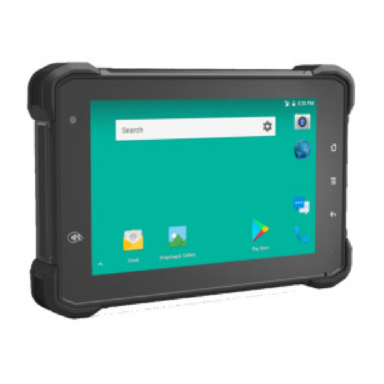
- Page 1 RVT-7 7” Rugged Android Vehicle Display Terminal User’s Manual Version 1.0.0...
- Page 2 We recommend that you keep one copy of this manual for the quick reference for any necessary maintenance in the future. Thank you for choosing Seatronx products.
-
Page 3: Table Of Contents
2.3.2 Checking the Battery Level ................. 17 2.3.3 Installing/Replacing the Battery ................18 2.4 Optimizing Battery Life ....................18 Chapter 3. Using RVT-7 hardware interface..................19 3.1 Transferring Files Between Computer and The Device ............ 19 3.1.1 Connection ......................20 3.2 Using Serial Port Demo App ..................... - Page 4 Declaration of Conformity The CE symbol on your product indicates that it is in compliance with the directives of the Union European (EU). A Certificate of Compliance is available by contacting Technical Support. This product has passed the CE test for environmental specifications when shielded cables are used for external wiring.
- Page 5 ► For pluggable equipment, the socket outlet should be near the equipment and should be easily accessible. ► Keep this equipment away from humidity. ► Disconnect this equipment from the A/C outlet before cleaning it. Use a moist cloth. Do not use liquid or sprayed detergent for cleaning. ►...
- Page 6 This product is warranted to be in good working order during the warranty period. Should this product fail to be in good working order at any time during this period, we will, at our option, replace or repair it according to Seatronx After-Sale-Service terms. This warranty does not apply to products damaged by misuse, modifications, accident or disaster.
-
Page 7: Product Highlights
Chapter 1: Introduction 1.1 Product Highlights ● Qualcomm Quad-Core, Cortex A7, 1.1GHz Processor ● Android 7.1.2 Operation System ● comply with IP-66 rating ● WIFI, Bluetooth, LTE, GNSS and 5000mAh rechargeable battery supported ● 7” IPS Display, physical 1280x800 resolution, 800cd/m2, Touch Multi-touch ●... -
Page 8: Extended Cable Definition
1.3 Extended Cable Definition 1.3.1 Standard version Item Definition Pogo pin GPIO69 GPIO1 GPIO GPIO GPIO4 RXD0 TXD0 RXD1 TXD1 VUSB Com 2 RS232 /dev/ttyHSL1. Com 1 RS232 /dev/ttyHSL0. ACC Input Connect with vehicle ACC power. Voltage range: 0-30V. Ps: With ACC function, the device is requested to connect the power source via DC adaptor simultaneously to power on after ignition. -
Page 9: Obd-Ii Version
0-3.7V Input 1 Input 2 Output 1 Output 2 USB Type-A(can not be used simultaneously with USB Type-C on the device) 1.3.2 OBD-II version Item Definition Pogo GPIO69 GPIO1 GPIO2 GPIO3 GPIO4 RXD0 TXD0 RXD1 TXD1 VUSB OBD-II Reserved Reserved Chassis Signal CAN_H... -
Page 10: Sae J1939 Version
Reserved Reserved Reserved Reserved CAN_L line L_line Permanent negative of ISO according Positive line of SAE 15765-4 to ISO voltage J1850 9141-2 and 14230-4 RS232 /dev/ttyHSL0. Connect with vehicle ACC power. input Voltage range: 0-30V. Ps: With ACC function, the device is requested to connect the power source via DC adaptor simultaneously to power on after ignition. - Page 11 VUSB J1939 Protocol”High”L Protocol”Low” Battery Battery CAN/ CAN/ CAN/J1939 Minus Plus J1939 J1939 shield ine,i.e Line,i.e (Ground) (+V) High CAN/J1708/J19 CAN/J1708/J1 39 High 939 Low RS232 /dev/ttyHSL0. Connect with vehicle ACC power. input Voltage range: 0-30V. Ps: With ACC function, the device is requested to connect the power source via DC adaptor simultaneously to power on after ignition.
-
Page 12: Specifications
1.4 Specifications Durability Features IP-66 Certified 1.5m (5ft.) drop-resistance Raised bezel for LCD impact protection LCD Display Size/Type 7" Digital IPS Panel Resolution 1280 x 800 Brightness 800 cd/m2 Touch screen Type Capacitive Multi-touch System Qualcomm 4xARM Cortex A7, 1.1GHz Processor Android v7.1.2 Memory LPDDR3 2GB... - Page 13 LTE FDD: B1/B3/B8 LTE TDD: B38/B39/B40/B41 CN Version TDSCDMA: B34/B39 China/India EVDO/CDMA: BC0 WCDMA: B1/B8 GSM: 900/1800MHz LTE FDD: B1/B3/B8/B18/B19/B26 JPN Version LTE TDD: B41 Japan WCDMA: B1/B6/B19 LTE-FDD Data Max 150Mbps(DL)/Max 50Mbps(UL) Transmission LTE-FDD Max 130Mbps(DL)/Max 35Mbps(UL) DC-HSPA+ Max 42 Mbps(DL)/Max 5.76Mbps(UL) 802.11a/b/g/n 2.4GHZ&5GHZ Support Wake-on-WLAN (WoWLAN)
- Page 14 SD Slot 1 x Micro SD card, 1.8v / 2.95v, up to 64G SIM Socket 1 x Mini SIM Card slot, 1.8v / 2.95v Gpio×2 Input, Gpio×2 Output (See "3. 4Extended Cable Definition" for GPIO details.) (See "3.3 Extended Cable Definition" for details.) I/O Interface (J1939 /OBD-II version) Serial Port 1 x RS232...
-
Page 15: Chapter 2: Getting Started
1. Power on by pressing the button: Long press the power button for more than 2 seconds until the Logo displayed. It needs around 40 seconds to start the system. The indicator is on when RVT-7 activate normally. 2. Power on by connecting ACC, see the details in Chapter “3.3 Using ACC”. -
Page 16: Installing Microsd And Sim Card
It makes the battery to be stored after fully charged. This excellent design is very beneficial for extending the life of the RVT-7 battery and ensuring the safety in use. 2.3.1 Charging with the Power Adapter To charge the battery with the provided power adapter: a. -
Page 17: Checking The Battery Level
The RVT-7 could be charged by a 5V2A and above USB charger via USB type- C cable. Warning: a. Please ensure that the input voltage of the DC interface is within the range of 8V-36V, or use the 12V adapter coming with device. If the input voltage of the DC is outside this range, the RVT-7 may be unable to charge or damaged. -
Page 18: Installing/Replacing The Battery
2.4 Optimizing Battery Life If the RVT-7 is unable to keep charging by DC power supply, to optimize the operating time of the battery, it is recommended that you do the following: Decrease the LCD display brightness. -
Page 19: Chapter 3. Using Rvt-7 Hardware Interface
To access the battery settings page, swipe down the Status Bar in the upper right corner and then tap and hold the BATTERY tile. Chapter 3. Using RVT-7 hardware interface 3.1 Transferring Files Between Computer and The Device You can transfer files, such as pictures or audio files, between your computer... -
Page 20: Connection
and your device using the provided USB cable. 3.1.1 Connection Connect the device to the computer by using the USB type-c cable, and open the prompt message of the device. The following interface displays. Click “USB charging this device”to charge. Then select “Tranfer files". -
Page 21: Using Serial Port Demo App
3.2 Using Serial Port Demo App Serial Port ID: COM1, COM2 Correspondence between RS232 tail line and device node. COM1=/dev/ttyHSL0. COM2=/dev/ttyHSL1. 1. The boxes in red means the text box for the COM port info. received, to display info received by corresponding COM port. 2. -
Page 22: Using Acc
3.3 Using ACC Please see “1.3 Extended cable definition” for ACC Interface details. 3.3.1 ACC Connection Instruction Figure 1-1, connecting the tablet with vehicle power supply through extended cable or docking station, and connecting ACC wire on extended cable of the tablet with ACC of vehicle. -
Page 23: Acc Settings Path
3.3.3 ACC Settings Path ACC settings located in ACC Settings under the category of System in the Settings of Android OS. Please refer to Figure 2-1, 2-2 and 2-3. Figure 2-1 Figure 2-2 Figure 2-3... -
Page 24: Acc Settings
3.3.4 ACC Settings ACC settings as shown in Figure 2-4 & Figure 2-5. Mark 1: The main switch of the three functions controlled by ACC, namely, light up the screen, close the screen and shut down. Mark 2: The switch of close screen function controlled by ACC. Mark 3: Click to pop-up dialog box as shown in Figure 2-6, to edit the screen off delay time after ACC outage. -
Page 25: Using Gpio
3.3.2 GPIO Typical Connection The following figure is a typical connection method of GPIO. In order to ensure the data communicate normally, please connect the GPIO interface of RVT-7 as shown in the following figure. GPIO Cable Gpio output Gpio input... -
Page 26: Gpio Specification
3.3.3 GPIO Specification RVT-7 GPIO specification Descriptions PINs Wire Description Logic TYP. Max Unit Note Color Symbol GPIO1 Red Digital Input Positive Trigger input GPIO2 While Digital Input Positive Trigger input GPIO3 Green Digital Internal weak Output pull-up GPIO4 Yellow... - Page 27 Figure 2-2 The button marked with a red box in Figure 2-3. It's used to read the level state of GPIO ports simultaneously when the directions are IN, and update to display on the corresponding buttons of State column; The criticality of high-low level is about 0.78V, it will display HIGH when more than 0.78V, and display LOW when less than 0.78V.
- Page 28 Figure 2-4...
-
Page 29: Using Nfc Function
3.5 Using NFC Function 3.5.1 NFC Activation Method Following the Figure 1 to Figure 3 to activate the NFC function. Figure 1 Figure 2 Figure 3... -
Page 30: Nfc Usage Demo
3.5.2 NFC Usage Demo When the NFC function activated, place the NFC card close to the induction area (as Figure 4 shows). A prompt tone would be heard if the card is successfully identified. If the card contains some information (such as manufacturer’s information), a interface as Figure 5 would be popped up. - Page 31 2. The root switch setting interface is as follows. In the figure, “1” is the Root permission (on/off) switcher. In the figure, “2” is the dialog entry of the password required to modify the function. Initial password: qwertyuiop 3. The dialog to set the Root Permissions (on/off)
-
Page 32: Obd Interface (Optional)
3. Dialog for modifying the password required for the root permission (on/off) status Note: The state of the root switch will be reset to off after the factory settings are restored, and the password will be restored to the initial password. 3.7 OBD Interface (optional) 3.7.1 Overview The OBD-II interface of PC-7146 is recommend for car and commercial vehicle... -
Page 33: J1939 Interface (Optional)
3.7.3 Application fields Academic project Vehicle diagnostic scanning tools Digital dashboard Fleet tracking and management OBD data-logging recorde 3.8 J1939 Interface (optional) 3.8.1 Overview The J1939 interface of PC-7146 is recommend for heavy-duty truck applications. And supports SAE J1939 and SAE J1708/J1587 protocols. SAE J1939 (hereinafter referred to as J1939) is the recommendation of Society of Automotive Engineers (SAE), which provides a standard architecture for communications between electronic components on medium-heavy vehicles. -
Page 34: Chapter 4. Docking Station Using Instruction
Chapter 4. Docking station Using Instruction 4.1 Docking station install steps 4.1.1 Align the RVT-7 to the limit slot of docking station as Fig 4.1 shown. Fig. 4.1 4.1.2 Pull the Buckle up as the fig.4.2 shown. Fig. 4.2 4.1.3. Push RVT-7 to make it attached the docking via snap joint. - Page 35 4. Release and finish the installation as fig.4.3 shown. Fig 4.4 4.2 Docking station Disassembly steps 4.2.1 Stretch upwards the buckle to release it from the device, as fig 4.5 shown. 4.2.2. Take out the device as Fig.4.6 pulling the top half out of the Fig.
-
Page 36: Chapter 5 . Accessories
Chapter 5 . Accessories 5.1 Opetional accessories (Choose 1 of 3) 1. Docking station (standard) 1 pc USB to Type-C cable 1 pc DC12V adapter for standard version 1 pc 2. Docking station (J1939) 1 pc USB to Type-C cable 1 pc 3.
Need help?
Do you have a question about the RVT-7 and is the answer not in the manual?
Questions and answers