Table of Contents
Advertisement
Advertisement
Table of Contents

Related Manuals for Akern BIA 101 BIVA PRO

Summary of Contents for Akern BIA 101 BIVA PRO
- Page 1 Instruction manual...
- Page 2 INSTRUCTION MANUAL Read this instruction manual carefully and keep it on hand for future consultation. The information in this document is subject to revision without notice. Visit the website for the latest versions. All rights reserved. No part of this document may be photocopied, reproduced or translated into other languages without prior written consent.
-
Page 3: Table Of Contents
INSTRUCTION MANUAL CONTENTS CONTENTS ............................3 CHAPTER 1: GENERAL AND SAFETY INFORMATION ................5 ................................... 5 NTENDED ..............................5 NTENDED TAFF ..............................5 NTENDED LACE OF ....................................5 ISUSE ............................... 6 EFINITIONS AND YMBOLS ............................ 6 LECTROMAGNETIC OMPATIBILITY ................................7 AFETY ARNINGS .............................. - Page 4 INSTRUCTION MANUAL ..................................53 LEANING ..................................53 TORAGE ............................54 AINTENANCE AND EPAIR ..................................54 ISPOSAL CHAPTER 6: TROUBLESHOOTING FOR COMMON PROBLEMS ..............55 BIA101 BIVA PRO S ........................... 55 YSTEM LERTS ....................56 F MEASUREMENTS ARE INACCURATE OR UNINTELLIGIBLE ..........................
-
Page 5: Chapter 1: General And Safety Information
Data obtained using BIA101 BIVA PRO may only be interpreted for therapeutic, clinical or diagnostic purposes by suitably qualified health professionals. Akern S.r.l. (hereinafter “Akern”) declares that the device, used as described in this manual and within the limits set out in sections 1.7 Safety Warningsand 0 Precautions and Warnings, has been designed and manufactured to have no effect on the patient's clinical condition and to ensure the safety of the patient, user or any third parties. -
Page 6: Efinitions And Ymbols
INSTRUCTION MANUAL 1.5 D EFINITIONS AND YMBOLS 1.5.1 Definitions Rz (Ohm): Electrical resistance. Defines a conductor’s opposition to the flow of an alternating electric current. Value in Ohms. Xc (Ohm): Capacitive Reactance. Defines the opposition of a capacitor to the flow of an alternating electric current. -
Page 7: Safety Warnings
INSTRUCTION MANUAL 60601-1-2, as required by directive 93/42/EEC as amended. 1.7 S AFETY ARNINGS This section describes the precautionary measures recommended to restrict the risks due to use of the device. Please familiarise yourself with this information to ensure the safety of procedures when using this device, in order to minimise the risk related to its use. - Page 8 • Do not replace batteries without contacting Akern or an authorized dealer. Lithium batteries have a high explosion risk if not correctly recharged. Remark: To replace the battery contact the Technical Support Service or Authorised Dealer Rev.
-
Page 9: Normative References
INSTRUCTION MANUAL Important! The lithium-ion battery may explode if handled incorrectly. Do not remove it or throw it away. Lithium-ion batteries must be disposed of in compliance with statutory legislation. Ref. Italian Legislative Decree no. 188 of 20 November 2008, as amended by Legislative Decree no. -
Page 10: Clinical Validation
Notified Bodies. 1.11 A PPLIED ARTS Akern defines the BIATRODES / BIVATRODES electrode as the only type BF applied part in direct contact with the subject. Rev. 0 dated 09/2020 Pages 10 to 67... -
Page 11: Chapter 2: Device And Accessories
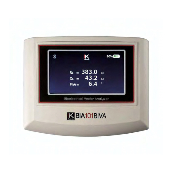
INSTRUCTION MANUAL CHAPTER 2: DEVICE AND ACCESSORIES 2.1 D ESCRIPTION OF THE EVICE Figure 1: BIA101 BIVA PRO front panel The BIA101 BIVA PRO has a 5” touchscreen display. To ensure correct touchscreen operation, remember to try not to scratch it, and not to use pens, pencils or other objects with sharp tips. - Page 12 INSTRUCTION MANUAL Figure 2: BIA101 BIVA PRO connection panel Remark: To connect a tester or a patient cable correctly, point the connector in the direction shown in the diagram below, then fit the connector into the panel, pressing gently until it clicks into place. To disconnect the cable/tester from the panel, simply pull the connector towards you.
-
Page 13: Description Of Accessories
INSTRUCTION MANUAL 2.2 D ESCRIPTION OF CCESSORIES The device is supplied complete with the following accessories: • BIATRODES™ / BIVATRODES™ electrodes • Total Body four-pole cable / Total Body BIVATRODES cable • Regional four-pole cable / Regional BIVATRODES cable • Battery charging power distribution unit •... - Page 14 INSTRUCTION MANUAL All devices produced by Akern are tested and calibrated with relation to the physical specifications of these two types of electrodes, which provide the user with a stable, accurate measurement. The quality and technical characteristics of the contact electrode are of critical importance for correct reading of the bioimpedance values and to ensure the device retains its performance characteristics, as defined in the risk analysis.
- Page 15 INSTRUCTION MANUAL Total Body four-pole cable Blue splitter: HAND electrode terminals Grey splitter: FOOT electrode terminals Blue connector Figure 5: Total Body four-pole cable Four-pole patient cable for Total Body analyses using BIATRODES™ electrodes. The cable is fitted with 4 insulated red and black alligator clips, for connection to the electrodes. For bioimpedance measurement, the patient cable must be connected to the device via the connector marked BIA CABLE / CHARGE (Figure 2).
- Page 16 Total Body cable. The two colours are also used on the connection panel, to enable the user to connect each cable to the device correctly. BIA 101 BIVA PRO is also compatible with dedicated BIVATRODES™ patient cables. Total Body BIVATRODES cable Grey alligator clip : FOOT...
- Page 17 INSTRUCTION MANUAL Remark: The Total Body BIVATRODES cable can be recognised by the connector colour: blue for the Total Body cable and grey for the Regional one. The two colours are also used on the connection panel, to enable the user to connect each cable to the device correctly.
- Page 18 INSTRUCTION MANUAL 2.2.3 Battery charger power distribution unit Certified medical power distribution unit. The battery charger output is a controlled 12 Vdc signal. The permissible input is from 100 to 240 Vac. For instructions on charging the device, see point 5.2 Charging the Batteries. Figure 9: Battery charger 2.2.4 USB cable The BIA101 BIVA PRO device has a Mini-USB...
- Page 19 INSTRUCTION MANUAL 2.2.6 Tester BIA101 BIVA PRO has two Testers for regular checking of calibration. For more details concerning use, see point 5.4 Calibration and Testing. Figure 12: Calibration checking tester Rev. 0 dated 09/2020 Pages 19 to 67...
-
Page 20: Chapter 3: Use Of The Device
INSTRUCTION MANUAL CHAPTER 3: USE OF THE DEVICE 3.1 P RELIMINARY PROCEDURES First use : Before switching on the device, charge the battery and wait until it is completely charged. • It takes about two hours to charge the battery completely. •... -
Page 21: Home
INSTRUCTION MANUAL Figure 13: Autotest screen If all tests are completed correctly, after a few seconds the HOME screen (Figure 14) appears. 3.4 H Figure 14: Home screen The Total Body|BIA and Regional|BIA icons provide access to the biompedance analysis sections, Total Body and Regional respectively. -
Page 22: Clinic & Field Working Modes
INSTRUCTION MANUAL Access to REGIONAL | BIA Analysis is only enabled if this function has been purchased. The bottom right icon accesses the SETTINGS of the BIA101 BIVA PRO (§ 3.8 Settings Menu). 3.5 CLINIC & FIELD WORKING MODES The device offers two different working modes. CLINIC MODE →... -
Page 23: Total Body | Bia Analysis
INSTRUCTION MANUAL 3.6 T | BIA A OTAL NALYSIS Total Body Analysis allows real-time measurement of bioelectric parameters for assessment of the patient's overall body composition. Operating instructions: 1. Apply the Standard Operating Procedure (CHAPTER 4: STANDARD OPERATING PROCEDURE (SOP)) and place the electrodes on the right half of the patient’s body. - Page 24 INSTRUCTION MANUAL Resistance Rz Reactance (Xc): Phase Angle PhA To continue in FIELD mode press button and enter the data as prompted (§ 3.6.5 Total Body - Field Mode). To transfer the measurement data to the BODYGRAM™ DASHBOARD software at once, follow the instructions in point 3.6.3 Transferring data to the BODYGRAM™...
- Page 25 3.6.3 Transferring data to the BODYGRAM™ DESKTOP app via Bluetooth BIA 101 BIVA PRO is able to transmit the bioelectric values measured to the BODYGRAM™ DASHBOARD software via a Bluetooth protocol. Remark: Automatic data transfer to the analysis software is only enabled by BODYGRAM™...
- Page 26 INSTRUCTION MANUAL Windows - Access the Settings Menu of the PC being used - Click the Devices icon - Selection Bluetooth and other devices (Otherwise, click the Bluetooth from the Windows notifications centre in the bottom right corner) - Activate Bluetooth connectivity (if not activated) by moving the switch to ON - Click the "...
- Page 27 INSTRUCTION MANUAL ▪ After compiling all fields (Date, Time, Height, Weight), click the in the bottom left corner (Figure 16). Figure 16: New Assessment Window ▪ The software will automatically connect to the BIVA device paired previously (Figure 17). Figure 17: Pairing with the device Rev.
- Page 28 INSTRUCTION MANUAL ▪ Once paired, the device transmits the measurement data to the software (Figure 18). Click “Insert” to complete the transfer. Figure 18: Transferring data to BODYGRAM™ DESKTOP ▪ Save the data acquired on the BODYGRAM™ DESKTOP software. ▪ On completion of the transfer, the device returns to the HOME screen and switches off.
- Page 29 INSTRUCTION MANUAL ▪ Access BODYGRAM™ DASHBOARD online via the following link: https://bodygram.cloud/it. ▪ Locate in the patient folder to which the measurement is to be copied and click "New Assessment”. ▪ Compile the fields provided with the patient’s information and the data of the measurement made, and save.
-
Page 30: Regional Analyses | Bia
INSTRUCTION MANUAL Once the data have been entered in the fields available correctly, the SAVE button is enabled for saving the measurement and the paired information. Remark: The Total Body measurement will be saved in session “T1” of the device’s DATABASE, accessible from the Settings Menu (§... - Page 31 INSTRUCTION MANUAL Accesses CLINIC mode Accesses FIELD mode measurement measurement Figure 20: Regional Main 5. Select CLINIC or FIELD mode and access the Measurement screen (Figure 21). 3.7.1 Regional - Clinic Mode Selecting the icon in the Regional Main screen access Regional measurement in Clinic mode (Figure 21).
- Page 32 INSTRUCTION MANUAL specific region of the body. At the end of the analysis cycle, the screen shown in Figure 22 displays. Indicates that data can be transferred to the BODYGRAM™ DESKTOP software via Bluetooth Figure 22: Regional analysis completed correctly Selecting a box displays the summary of the data measured for the corresponding region (Figure 23).
- Page 33 INSTRUCTION MANUAL START GUIDE provided. • Run the BODYGRAM™ Desktop app on the PC and open the REGIONAL APP. • Locate in the patient folder to which the data are to be sent and click "New Assessment”. • After entering the data in the fields provided, click the symbol in the bottom left corner.
- Page 34 INSTRUCTION MANUAL If the memory is full, data should be transferred to the BODYGRAM™ DESKTOP software (§ 3.8.2 Importing the database to BODYGRAM™ DESKTOP via USB ). Figure 25: Regional Measurements - Field Screen To start the Regional analysis, press the button in the bottom right corner.
- Page 35 INSTRUCTION MANUAL Figure 27: Patient data form - Regional Field Once the data have been entered in the fields available correctly, the button is enabled for saving the measurement and the paired information. Once the measurement has been saved, the system automatically returns to the HOME screen. To view the saved measurement, access the Database from the Settings Menu.
-
Page 36: Settings Menu
INSTRUCTION MANUAL 3.8 S ETTINGS Touch from the Home screen to access the BIA101 BIVA PRO Settings. The following functions are available: DATABASE, FIRMWARE UPDATE, AUTOTEST. Firmware Autotest Update Database Figure 28: Settings Menu 3.8.1. Database REGIONAL TOTAL BODY DATABASE DATABASE Figure 29: Database Main: Regional –... - Page 37 INSTRUCTION MANUAL Regional Measurements Database Touch one of the display icons of the sessions available to access the list of sessions saved inside it (Figure 30). Scrolling arrows Figure 30: List of Regional measurements Use the “up” and “down” scrolling arrows to select the measurement required. After selecting the patient, touch on the right to access the measurement data (Figure 31).
- Page 38 INSTRUCTION MANUAL Total Body Measurement Database Touch next to session T1 (Figure 29) to access the list of Total Body measurements saved inside it (Figure 32). Use the “up” and “down” scrolling arrows to view the measurement required. Figure 32: List of Total Body measurements 3.8.2.
- Page 39 INSTRUCTION MANUAL Figure 33: Home BODYGRAM™DESKTOP In BIVA PRO manager, click IMPORT SESSION: Figure 34: BIVA PRO Manager Once imported, sessions can be viewed and accessed on the same page under the “Imported Sessions” heading (Figure 35). Each session is marked with the date and time of transfer to BODYGRAM™...
- Page 40 INSTRUCTION MANUAL Date and time of import Number of measurements saved in the session Figure 35: Imported sessions in BIVA PRO manager To pair the imported measurements with the patients in the BODYGRAM™ DESKTOP Database, click the session and access the list of saved measurements(Figure 36). Timestamp: date and time of the analysis made in FIELD mode Tag: ID assigned to the subject and...
- Page 41 INSTRUCTION MANUAL Figure 37: select/create new group Select a subject from those available or create a New Subject by clicking on "New Subject” Date of birth and gender saved on the device are automatically imported into the corresponding BODYGRAM™ fields. Figure 38: select/create new subject ...
- Page 42 Wait the update to be completed (Figure 39). Figure 39: Set device date and time 3.8.2. Firmware update The firmware may only be updated by authorised, skilled staff. Contact your Authorised Dealer or the Akern Technical Support Service. 3.8.3. Autotest start This function allows manual starting of the autotest, to check the correct operation of Batteries, Internal Functions and Sensor Calibration(§...
-
Page 43: Chapter 4: Standard Operating Procedure (Sop)
INSTRUCTION MANUAL CHAPTER 4: STANDARD OPERATING PROCEDURE (SOP) 4.1 P RELIMINARY INFORMATION a) Before every measuring session, check the device using the tester supplied (§ 5.4 Calibration and Testing). b) Measure the weight and height accurately with calibrated instruments approved for professional use (class III instruments are recommended). -
Page 44: Positioning The Electrodes
INSTRUCTION MANUAL The patient must be lying face upwards, as shown in Figure 40. This position also guarantees correct measurement in the case of subjects with BMI over 40 and on unclothed bedridden patients. Avoid contacts between the limbs and between the limbs and torso, which may modify the path of the measurement current. - Page 45 INSTRUCTION MANUAL HAND Proximal (sensor) electrode: position the electrode between the bony prominences of the radius and the ulna (in the centre of the imaginary ≥ 5 cm line midway between the radius and the ulna) → and connect the black alligator clip of the patient cable. Distal (injector) electrode: position the electrode on the back of the hand level with the metacarpals →and connect the...
- Page 46 INSTRUCTION MANUAL Central tang Figure 43: Adhesive side of BIVATRODES ™ HAND Point the central tang outward. Center the proximal area (sensor) of the electrode between the distal prominences of the radius and ulna Center the distal area (injector) of the electrode on the dorsal surface of the hand at the metacarpal level.
-
Page 47: Precautions And Warnings
. Do not make measurements with body temperature over 38°C. No therapy or treatment must be administered during measurement. Seek prior advice from the Akern Scientific Department for any conditions not covered here. 4.4.1 Application Advice for Special Cases ... - Page 48 30 years. The BIA 101 BIVA PRO device emits a current of 250 µA, well below the 500 µA, threshold recognised as critical for risks of interaction with other active devices. The device's safety analyses are included in the clinical validation document and technical file.
-
Page 49: Chapter 5: Device Maintenance
HARGING THE ATTERIES BIA 101 BIVA PRO must be recharged exclusively using the supplied power distribution unit, which is certified in compliance with EN 60601-1. The use of battery chargers not authorised by the producer leads to loss of warranty cover and could damage the device beyond repair and put the user and the patient being analysed at risk. -
Page 50: Calibration And Testing
INSTRUCTION MANUAL Figure 46: Device charging Complete charging takes about two hours. A battery charging control circuit inside the device prevents any overload risk. 5.4 C ALIBRATION AND ESTING Only qualified personnel are authorised to perform calibration using precision instrumentation, in compliance with procedures designed to minimize possible causes of measurement errors. - Page 51 It is important to check the reading of the nominal values covered by the tester before each measurement session. To ensure optimal efficiency and precision, Akern advises users to have the sensors checked in its laboratories every two years. 5.4.2. How to use the tester...
- Page 52 INSTRUCTION MANUAL CABLE connectors Switch on the device From the Home screen, select Regional | BIA, access Clinic model and start the analysis When the analysis is complete, wait a few seconds, then check that the reading is: a) within the tolerances shown on the blue tester (1) for the right half of the body b) within the tolerances shown on the grey tester (2) for the left half of the body Figure 48: Checking readings for right (a) and left (b) halves of the body...
-
Page 53: Cleaning
INSTRUCTION MANUAL Total Body BIVATRODES™ cable Connect the Total Body BIVATRODES cable to the device. Unscrew the cap of the blue tester (1) and fit the alligator clips of the patient cable as shown Figure 50Figure 49 . Figure 50: BIVATRODES cable - tester connection: a) rear of ... -
Page 54: Maintenance And Repair
AINTENANCE AND EPAIR The device has no User-serviceable parts. Service operations must be carried out solely by the Akern Technical Support Service or by a suitably trained Authorised Dealer. Contact your dealer for initial technical support, since he is able to provide a quick, efficient service. -
Page 55: Chapter 6: Troubleshooting For Common Problems
INSTRUCTION MANUAL CHAPTER 6: TROUBLESHOOTING FOR COMMON PROBLEMS Akern designs, produces and distributes medical devices with all activities controlled by a quality management system certified under the ISO 9001 and ISO 13485 standards. Statistical analysis of malfunctions shows that 90% of problems can be resolved by simple corrective actions by the user, or by contacting your Authorised Dealer. -
Page 56: I F Measurements Are Inaccurate Or Unintelligible
INSTRUCTION MANUAL 6.1.2 General Error The device performs an internal check on its functions at every switch-on, to prevent measurement errors. If an error is found, the following message appears. Figure 52: General Error This error appears when the device fails one or more of the internal checks. This error does not depend on external factors and cannot be corrected or resolved except by suitably trained staff. -
Page 57: I F The Device Will Not Switch On
If the device still fails to switch on even after charging the battery, contact the Akern Technical Support Service, through your Authorised Dealer. -
Page 58: Chapter 7: Technical Support And Service
The theoretical lifetime of the device as declared by Akern is 5 years, during which term the availability of replacement parts is guaranteed. Any damages arising due to the fault or negligence of Akern are covered up to the maximum amount of the list price of the device at the time of purchase. -
Page 59: Reporting Incidents Or Near Misses
(bubble wrap, adhesive tape, etc.). The device may be damaged by rough handling, pack with great care. Akern declines all responsibility for damage to the device in transit. The shipment should be insured; many couriers offer this service. -
Page 60: Chapter 8: Operating Principles
INSTRUCTION MANUAL CHAPTER 8: OPERATING PRINCIPLES 8.1 T HEORETICAL ASES OF IOIMPEDANCE NALYSIS BIA101 BIVA PRO is a vector impedance analyser for the analysis of hydration and nutritional status that can be used in both hospitals and clinics. The analysis performed by the BIA101 BIVA PRO device is conducted using the classic tetrapolar technique, with sinusoid current output at a frequency of 50 kHz. -
Page 61: B Do
INSTRUCTION MANUAL The Impedance (Z) of a human body is a function of its specific resistivity of its fat free tissue, which is a good conductor, its cross-section (a) and its length (L): where Z (impedance) is in Ohm, in Ohm/cm, L in cm and a in square cm. Considering the fat free mass as a cylinder, the equation can be rewritten with multiplication by L/L: where V = a*L is the volume of the bioelectric conductor. - Page 62 INSTRUCTION MANUAL Figure 54: BIA101 BIVA PRO functional block diagram The main components are: • • Sensor circuit board Power supply control circuit board • • 5” capacitive touchscreen display Metal multipole connector • • Display/Digital/UI circuit board Bluetooth® BLE module •...
-
Page 63: Chapter 9: Technical Specifications
INSTRUCTION MANUAL CHAPTER 9: TECHNICAL SPECIFICATIONS DEVICE TYPE Vectorial bioimpedance analyser MODEL BIA101 BIVA PRO RESISTANCE (Rz) 0 – 1000 Ohm Range () Resolution 0.1 Ohm Accuracy REACTANCE (Xc): Range () 0 – 200 Ohm Resolution 0.1 Ohm Accuracy POWER SUPPLY Li-ion battery 7.4 V 2600 mAh Battery charger supplied... -
Page 64: Chapter 10: Declaration Of Conformity
3 of annex VII. Notified Body BUREAU VERITAS ITALIA S.p.A. Viale Monza, 347 20126 Milan - Italy Conformity marking YANN INGHILESI GIALLONI 1370 Chief Executive Officer Akern S.r.l. Rev. 0 dated 09/2020 Pages 64 to 67... -
Page 65: Chapter 11: Contents Checklist
INSTRUCTION MANUAL CHAPTER 11: CONTENTS CHECKLIST 11.1 BIA101 BIVA PRO DEVICE CHECKLIST With BIATRODES™ electrodes Art no. Item 0CB12-004 Battery charger 12 Vdc 0CP4-004 Four-pole Total Body patient cable 4 spare alligator clips 0ELB100 BIATRODES™ electrodes 0MBT USB/Bluetooth accessory 0CUSB-01 Mini-USB cable 0TEST00D Total Body tester circuit... -
Page 66: Regional Kit Checklist
INSTRUCTION MANUAL 11.2 R EGIONAL HECKLIST With BIATRODES™ electrodes Art no. Item 0CP4-005 Regional four-pole patient cable 4 spare alligator clips 0ELB100 BIATRODES™ electrodes 0TEST00D-01 Regional tester circuit Regional App PIN Card Protective case Quick Start Guide Regional Kit With BIVATRODES™ electrodes Art no. - Page 67 Registered Office: Via Umberto Forti 6 - 56121 frazione Montacchiello, Pisa (PI), Italy Operational Site: Via Lisbona 32/34 - 50065 Pontassieve (Florence, Italy) Tel. +39 055.8315658 akern@akern.com | www.akern.com This product meets the following requirements: Medical device directive 93/42/EEC as amended ...
Need help?
Do you have a question about the BIA 101 BIVA PRO and is the answer not in the manual?
Questions and answers