Advertisement
ITS 300 & 500 SERIES POSITION MONITORING SWITCH
ITS 300 & 500 SERIES POSITION MONITORING
SWITCH
INSTALLATION AND OPERATION MANUAL
(Explosion proof Ex d IIC T6)
(Doc no: ITS00312-M)
74-6, Chun Ui-Dong, Won Mi-Gu, Bucheon City, Kyoung Ki-do, Korea
Tel : 82-2-855-1365, 66 Fax : 82-2-855-1367 E-mail :
roy75@i-tork.com
Position monitoring switch ITS300 & 500 series
Installation and operating manual (ITS-00312-M)
1 1 1 1
Advertisement
Table of Contents

Summary of Contents for I-Tork ITS 300 Series
- Page 1 (Explosion proof Ex d IIC T6) (Doc no: ITS00312-M) 74-6, Chun Ui-Dong, Won Mi-Gu, Bucheon City, Kyoung Ki-do, Korea Tel : 82-2-855-1365, 66 Fax : 82-2-855-1367 E-mail : roy75@i-tork.com Position monitoring switch ITS300 & 500 series Installation and operating manual (ITS-00312-M) 1 1 1 1...
-
Page 2: Table Of Contents
ITS 300 & 500 SERIES POSITION MONITORING SWITCH TABLE OF CONTENTS 1. INTRODUCTION 2. MANUFACTURER WARRANTY 3. PRODUCTION DESCRIPTION 4. LABEL DESCRIPTION 5. SUFFIX SYMBOLS 6. SPECIFICATION 7. PARTS AND ASSEMBLY 8. DIMENSION 9. INSTALLATION 10. CONNECTION – POWER Position monitoring switch ITS300 & 500 series Installation and operating manual (ITS-00312-M) 2 2 2 2... -
Page 3: Introduction
God, failure due to power surge, and cosmetic damage. Improper or incorrectly performed maintenance or report voids this Limited Warranty. For detailed warranty information, please contact the corresponding local I-Tork distributors or main office in Korea. -
Page 4: Production Description
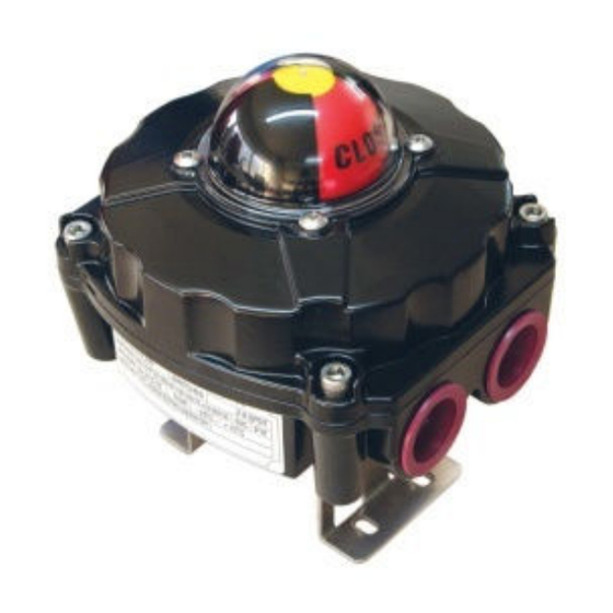
ITS 300 & 500 SERIES POSITION MONITORING SWITCH 3. PRODUCTION DESCRIPTION ITS300/500 position monitoring switch is used for the valve and actuators which rotate 90 degree’s quarter turn. The first function of ITS300/500 is to provide visual indication of current position of valve and actuator. -
Page 5: Suffix Symbols
ITS 300 & 500 SERIES POSITION MONITORING SWITCH 5. Suffix Symbols 6. Specification Position monitoring switch ITS300 & 500 series Installation and operating manual (ITS-00312-M) 5 5 5 5... -
Page 6: Parts And Assembly
ITS 300 & 500 SERIES POSITION MONITORING SWITCH 7. Parts and Assembly COVER INDICATOR INDICATOR O-ring COVER BOLT COVER SHAFT O-ring MICRO SWITCH BODY TERMINAL BLOCK E-ring 8. Dimensions CONTROLS Warning 9. INSTALLATION Saftey Warning All input and supply pressure to valve, actuator, and other related devices must be turned off when installing. -
Page 7: Connection - Power
ITS 300 & 500 SERIES POSITION MONITORING SWITCH ITS300/500 is designed for use in explosive gas atmosphere. The end-user must follow the explosion proof procedures and safety precautions. Please make sure there is no explosive gas or material present before the installation. Caution : In order to avoid unexpected accident, serious injury and property damage, make sure to cut all power supply to the actuator and valve before inspection, maintenance and repair , Ambient temperature : C ~+60... - Page 8 ITS 300 & 500 SERIES POSITION MONITORING SWITCH Ground Connection: Ground Connection is provided on the external surface. This Connection should be used to connect the enclosure metal work to the Equi-potential Bonding System/Earth. This is in addition to any Protective Earth Terminals provided inside the enclosure. It must be sized in accordance with local rules for electrical installations and not be smaller than 4㎟.
- Page 9 ITS 300 & 500 SERIES POSITION MONITORING SWITCH Position Transmitter Type MECHANICAL SWITCHES 15~28VDC OPEN SWITCH LOAD Output 4~20mA CLOSE SWITCH GROUND Adjustment – Upper CAM Push down the Upper Cam (Green - Open) and turn right or left to the preferred position until the switch is activated and release the cam;...
- Page 10 ITS 300 & 500 SERIES POSITION MONITORING SWITCH Rating Table for ITS300 & ITS500 Wire Standard Position monitoring switch ITS300 & 500 series Installation and operating manual (ITS-00312-M)
Need help?
Do you have a question about the ITS 300 Series and is the answer not in the manual?
Questions and answers