Table of Contents
Advertisement
Available languages
Available languages
Quick Links
Advertisement
Chapters
Table of Contents

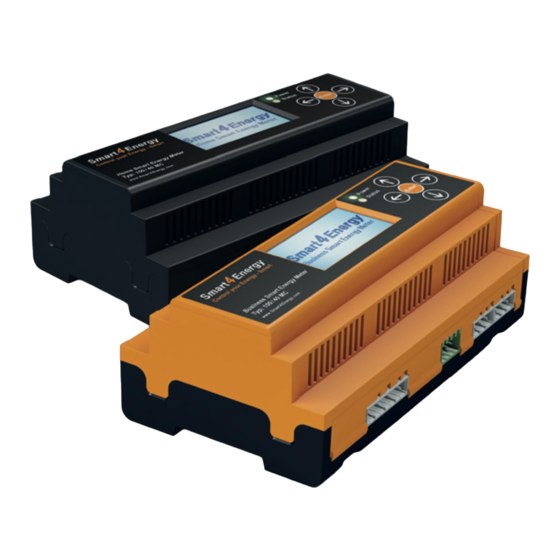
Summary of Contents for Smart4Energy Business Smart Energy Meter 100/40 MC
- Page 1 Stand: Juni 2015 SMART ENERGY METER Benutzerhandbuch User Guide...
-
Page 2: Table Of Contents
I N h A lT S V E R Z E I C h N I S 1. Vorwort ........... 5 2. - Page 3 1 . V o R w o R T 9.2 Einstellung des Datums ........24 Sehr geehrte Kundin, sehr geehrter Kunde, 9.3 Einstellung der Zeit .
-
Page 4: Einleitung
2 . E I N l E I T U N G 3 . V E R w E N d E T E S Y M B o l E Diese Dokumentation unterstützt Elektrofachkraft und Nutzer bei der Montage, Inbetriebnahme In dieser Anleitung werden folgende Arten von Sicherheitshinweisen und allgemeine sowie Konfiguration des Smart Energy Meter. -
Page 5: Wichtige Hinweise
4 . w I C h T I G E h I N w E I S E 4.1.2 Qualifikation des Fachhandwerks In Verbindung mit dieser Bedienungsanleitung sind weitere Unterlagen gültig. Für Schäden, die durch Nichtbeachtung dieser Anleitungen entstehen, wird keine Haftung übernommen. Die Installation des Smart Energy Meter darf nur von einer anerkannten Elektrofachkraft durchge- führt werden. -
Page 6: Messgenauigkeit
5 . G E R äT E ü B E R S I C h T 4.1.5 Messgenauigkeit 5.1 Produktetikett ACHTUNG: Die vom Smart Energy Meter gesammelten Daten können von den erfassten Daten des Stromzählers abweichen. Die Daten des Smart Energy Meter sind nicht für Abrechnungszwecke geeignet. -
Page 7: Abmessungen
5.2 Abmessungen 5.3 Anschlüsse 160 mm Beschreibung: Klemme: Messwandlerbuchse 20 A – 100 A Messwandler - Eingang (anhängig vom Gerätetyp) -X5a bis -5e USB-Port Schnittstelle für Firmware-Update RJ-45 Buchse Schnittstelle für RS485 und CAN-Bus DIP Schalter CAN-Bus (Abschlusswiderstand wählbar) RS485 (Abschlusswiderstand wählbar) Power Buchse Netzanschlussbuchse L &... -
Page 8: Anschlussbezeichnung
6 . M o N TA G E 5.4 Anschlussbezeichnung 6.1 Montage auf DIN-Hutschiene -X5a -X5b -X5c -X5d -X5e DIN-Hutschiene: -X12 Setzen Sie das Gerät gemäß Abbildung auf die Arretieren Sie das Gerät mit dem Hutschienenhalteclip. Hutschiene auf. 6.2 Wandmontage Der Smart Energy Meter kann mit Hilfe der integrierten Hutschienenhalteclips gemäß... -
Page 9: Anschlusspläne
7 . A N S C h l U S S p l ä N E 7.1 Anschlussschema Smart Energy Meter 7.2 Spannungsversorgung / Anschlussplan (Darstellung der vereinfachten Funktionsweise) Mess- Mess- wandler wandler N EO ZE D Verbraucher 230 V 0 1 5 3 2 -X12 Smart Energy Meter... -
Page 10: Stromwandler / Anschlussplan
7.3 Stromwandler / Anschlussplan 7.4 Verkabelungsbeispiel E V U- Üb e rga be p un k t Ve r b r au c he r Wandler 40 A* schwarze Ader Wandler Wandler 40 A* Wandler Wandler Wandler 100 A* Wandler 100 A* 40 A* 40 A*... -
Page 11: Kommunikation / Schnittstellen
7.5 Kommunikation / Schnittstellen RS485 Schnittstelle CAN-Bus Schnittstelle Ein 120R Abschlusswiderstand kann wahlweise zugeschaltet werden. Dies geschieht über den Die Belegung der CAN-Bus Schnittstelle kann den folgenden Abbildungen entnommen werden: Schalter -S1 (siehe Abbildung). Funktion: Rx / Tx - (RS458 B) Rx / Tx + (RS458 B) CAN-L CAN-H... -
Page 12: Menü
8 . M E N ü Smart Energy Meter Menüführung (Deutsch) Relaiskontrolle Relais 1 Relais 2 EVU-Übergabepunkt L1 Leistung in 0.0 kW Menüsprache Weitere Infos Bus-Adressen Info EVU-Statistik Hauptinformation Kanal-Übersicht Input 1 Input 20 L2 Leistung in 0.0 kW L3 Leistung in 0.0 kW Englisch XXXXX... -
Page 13: Inbetriebnahme
9 . I N B E T R I E B N A h M E 9.3 Einstellung der Zeit Es wird davon ausgegangen, dass das Gerät ordnungsgemäß angeschlossen und mit allen relevanten Komponenten verbunden ist. • Navigieren Sie aus der Ansicht "Hauptinformation" zum Menüpunkt "Neue Zeit" und bestätigen Sie mit "Enter". -
Page 14: Passwort Vergeben
9.5 Passwort vergeben 9.7 Konfiguration der Kanäle ACHTUNG: Im Auslieferungszustand ist das Gerät nicht mit einem Passwort versehen. Ein Passwort richten Sie wie folgt ein: Ist der Meter mit einem Monitor, Datenlogger oder Manager verbunden, • Navigieren Sie über Ansicht "Sicherheit" zum Eintrag "Passw. setzen" (siehe Kapitel 8: "Menü"). können die Kanalbezeichnungen über die Weboberfläche geändert werden! •... -
Page 15: Aktualiserung Der Firmware
Das Gerät ist wartungsfrei. Bei Schäden, z.B. durch Transport und/oder Lagerung, dürfen keine Dieses Programm und weiterführende Informationen finden Sie unter: Reparaturen durch Fremdpersonal vorgenommen werden. Beim Öffnen des Geräts erlischt der www.smart4energy.com. Gewährleistungsanspruch. 1 1 . R E I N I G U N G 1 3 . -
Page 16: Technische Daten
1 5 . T E C h N I S C h E d AT E N Business Smart Energy Meter Home Smart Energy Meter Typ: 100/40 MC , 100/100 MC, 400/100 MC, 400/400 MC Typ: 100/20 MC, Typ: 100/40 MC ALLGEMEINE DATEN ALLGEMEINE DATEN Netzspannung / Netzfrequenz:... -
Page 17: Gewährleistung
Bearbeitung des Vorgangs bemühen. Sollten Sie Fragen haben oder weitere Informationen benötigen, dann kontaktieren Sie uns unter der Rufnummer +49 (0) 2484 / 918 292 oder per E-Mail: rma@smart4energy.com. Benutzerhandbuch Smart Energy Meter... -
Page 18: Haftungsausschluss
EG-Konformitätserklärung Abweichungen nicht ausgeschlossen werden. Es wird keine Gewähr für Vollständigkeit gegeben. Die jeweils aktuelle Version ist im Internet unter www.smart4energy.com abrufbar oder über die üblichen gemäß der EG-Richtlinie 2004/108/EG (elektromagnetische Verträglichkeit) Vertriebswege zu beziehen. Gewährleistungs- und Haftungsansprüche bei Schäden jeglicher Art sind vom 15. - Page 19 2 0 . N o T I Z E N TA B l E o F C o N T E N T S 1. Foreword ..........39 2.
-
Page 20: Foreword
1 . F o R E w o R d 8. Menu........... . 56 Dear Customer, 9. -
Page 21: Introduction
2 . I N T R o d U C T I o N 3 . S Y M B o l S U S E d This documentation provides support to electricians and users in the assembly, commissioning The following types of safety information and general notices are used in this Guide: and configuration of the Smart Energy Meter. -
Page 22: Important Information
4 . I M p o R TA N T I N F o R M AT I o N 4.1.2 Installation by qualified electrician Additional documents are applicable in connection with this User Guide. No liability is assumed for any damage sustained by failure to observe these instructions. -
Page 23: Measurement Accuracy
5 . d E V I C E o V E R V I E w 4.1.5 Measurement accuracy 5.1 Product label WARNING: The data collected by the Smart Energy Meter may deviate from the data captured by the electricity meter. The data of the Smart Energy Meter are not suitable for billing purposes. -
Page 24: Dimensions
5.2 Dimensions 5.3 Connections 160 mm Description: connector block Measuring transducer jack 20 A – 100 A measuring transducer – input (depends on device type) -X5a bis -5e USB port Interface for firmware update RJ-45 jack Interface for RS485 and CAN bus DIP switch CAN bus (terminal resistor selectable) RS485 (terminal resistor selectable) Power jack... -
Page 25: Connection Designation
6 . I N S TA l l AT I o N 5.4 Connection designation 6.1 Installation on DIN top-hat rail -X5a -X5b -X5c -X5d -X5e DIN top-hat rail: -X12 Position the device on the top-hat rail as shown in the Fix the device using the top-hat rail retaining clip. -
Page 26: Connection Diagrams
7 . C o N N E C T I o N d I A G R A M S 7.1 Smart Energy Meter connection diagram 7.2 Power supply / Connection diagram (simplified mode of function shown) Measuring Measuring transducer transducer N EO ZE D Consumer... -
Page 27: Current Transducer / Connection Diagram
7.3 Current transducer / Connection diagram 7.4 Wiring example Ele ct r icity tr a nsfe r p oi nt Con su m e r Transducer 40 A* Transducer black wire Transducer Transducer 40 A* Transducer Transducer 100 A* Transducer Transducer 100 A* Transducer... -
Page 28: Communication / Interfaces
7.5 Communication / Interfaces CAN-Bus interface The following figures show the assignment of the CAN bus interface: RS485 interface A 120R terminal resistor can be switched in optionally using the S1 switch (see diagram). Function: Rx / Tx - (RS458 B) Rx / Tx + (RS458 B) CAN-L CAN-H... - Page 29 8 . M E N U Smart Energy Meter menu navigation (English) Switches control Switch 1 Switch 2 Building Main Cable L1 Power in 0.0 kW L2 Power in 0.0 kW L3 Power in 0.0 kW menu language other information Bus adresses Info Main Cable statistics Global Information...
-
Page 30: Putting Into Operation
9 . p U T T I N G I N T o o p E R AT I o N 9.3 Setting the time It is assumed that the device is correctly connected and linked with all relevant components. •... -
Page 31: Assigning A Password
9.5 Assigning a password 9.7 Configuring the channels WARNING: On delivery the device does not have a password. A password may be setup as follows: If the Meter is combined with a Monitor, Data Logger or Manager, the cable names •... -
Page 32: Updating The Firmware
The warranty expires if the device is opened. www.smart4energy.com 1 3 . d E C o M M I S S I o N I N G 1 1 . -
Page 33: Technical Data
1 5 . T E C h N I C A l d ATA Business Smart Energy Meter Home Smart Energy Meter Type: 100/40 MC , 100/100 MC, 400/100 MC, 400/400 MC Type: 100/20 MC, Typ: 100/40 MC GENERAL DATA GENERAL DATA Mains voltage / mains frequency: 85 V... -
Page 34: Warrenty
2. Complete the RMA form carefully and remember that ALL mandatory fields must be completed! 3. Return the completed form to us by post or email (See Legal Notice: www.smart4energy.com). Within the next 3-5 working days you will receive a confirmation about the receipt of your form and your RMA number. -
Page 35: Liability Disclaimer
EC Declaration of Conformity deviations cannot be ruled out. No warranty for completeness is given. The current version may be downloaded from www.smart4energy.com or obtained from the usual distribution paths. Warranty In accordance with EC Directive 2004/108/EC (Electromagnetic Compatibility) and liability claims in the case of damage of any type are ruled out if they are attributable to one or... -
Page 36: Notes
2 0 . N o T E S User Guide Smart Energy Meter... - Page 37 LOKISA Smart Energy GmbH Phone: +49 (0) 24 84 / 918 292 Trierer Straße 53a Web: www.smart4energy.com 53894 Mechernich / Germany E-Mail: info@smart4energy.com...
Need help?
Do you have a question about the Business Smart Energy Meter 100/40 MC and is the answer not in the manual?
Questions and answers