Table of Contents
Advertisement
Quick Links
Helvest
Helvest
®
1. GENERAL PRODUCT PRESENTATION
1.1 What is the Helvest Flex system?
The Helvest Flex system is designed to easily assemble electronic circuits for the
control of a model railroad. Decoders can be made to manage switches, signals and
other accessories, presence detectors, and other future developments.
The HP100 motherboard is the heart of the system. It manages a maximum of three
modules, automatically identifying them and activating their specific functions.
There are two types of modules:
- "net" module: it communicates with other units, with the digital control unit or with
the PC (e.g. it manages the DCC digital signal to control the switches, or
communication buses to report the presence of trains).
- "Layout" module: manages the devices present on the layout (for example it moves
the switches or receives the data from the sensors that detect the presence
of the trains).
Layout
Layout
Plastico
Moduli Layout
The main advantages of the system are:
- You can configure it according to your needs by combining the additional modules
as you wish.
- It is extremely easy to make changes, modifications or updates to the modules.
- You can expand it with new modules that will be available in the future.
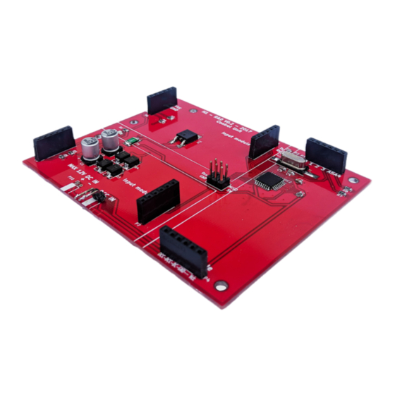
1.2 HP100 components
Flex HP100 user manual
Net
HP100
PC o centrale
The main parts of the board are identified in Figure 2:
1) Area for " Layout " type module for connection to the layout.
2) Area for " Net " type module for communication with the digital
control panel, the PC or other boards.
3) Connectors for the insertion of
"Layout" modules
4) Connectors for the insertion of the
"Net" module.
5) Mounting holes
6) Power supply connector
8) Power LED.
2 HELVEST FLEX SYSTEM BASIC
OPERATIONS
2.1 Mounting the board
Fig. 1
The complete board must be mounted in such a way that it DOES NOT
touch anything during operation. In particular, it
must not come into contact with any metallic or
flammable materials.
For temporary installations, it can be placed on a
non-flammable insulating surface (plastic, glass,
ceramic floor, etc...).
For fixed layouts, it is recommended to mount it by
screwing the HP-100 onto the wooden structure with
digitale
the screws and spacers provided (fig. 3). This
operation must be done before inserting the
additional modules.
2.2 Installing the additional modules
The installation of the additional modules must be carried out with the power supply
switched off.
You can install:
FleX Motherboard HP100 - User Manual
5
layout module 1
1
3
3
Reset
Power
8
layout module 2
1
3
5
3
6
Fig. 2
4
5
3
7
4
3
2
net module
5
4
Fig. 3
Advertisement
Table of Contents

Summary of Contents for Helvest FleX HP100
- Page 1 PC or other boards. 3) Connectors for the insertion of layout module 1 The Helvest Flex system is designed to easily assemble electronic circuits for the "Layout" modules control of a model railroad. Decoders can be made to manage switches, signals and 4) Connectors for the insertion of the other accessories, presence detectors, and other future developments.
- Page 2 Helvest FleX Motherboard HP100 - User Manual - a single “Layout” module, in If the wire is very thin, fold it up as in figure 5 on the sleeve to ensure good contact. Fig. 4 any of the available slots;...
- Page 3 4.2 Service and customer care If you have any questions about the products you can contact us via the form on the website www.helvest.ch, via email, and via social networks.
Need help?
Do you have a question about the FleX HP100 and is the answer not in the manual?
Questions and answers