Table of Contents
Advertisement
Advertisement
Table of Contents
Troubleshooting

Summary of Contents for Horizon Technology SPE-DEX 3100
- Page 1 ® SPE-DEX 3100 Oil & Grease Extractor Users Guide...
- Page 2 Website: www.horizontechinc.com Copyright © 2017 by Horizon Technology, Inc. All rights reserved. Horizon Technology, Inc. reserves the right to change the infor- mation in this document without notice. No part of this work may be processed, re- produced, or transmitted in any form or by any means, electronic or mechanical, including photocopying and recording, or by any information storage or retrieval sys- tem, except as may be expressly permitted in writing by Horizon Technology, Inc.
-
Page 3: Table Of Contents
Part I: Getting Started ........................9 Site Preparation and Unpacking ..................11 Preparing the Site ......................... 11 3.1.1 Facility Requirements ..................... 11 Unpacking the SPE-DEX 3100 Oil & Grease Extractor ..............12 Unpacking Checklist ........................15 3.3.1 3100 Controller Kit ......................15 3.3.2 Extractor Kit ........................ - Page 4 Step 1: Conditioning ........................36 Step 2: Load Sample ........................36 Step 3: Air Dry ..........................37 Step 4: Rinse ..........................37 Operation Procedures ......................39 Setting Up for Operation ....................... 39 Loading the SPE Disk ........................45 Running a Method ......................... 45 7.3.1 Running a Verification, Practice, or Standard Factory Method ........
- Page 5 B.1 SPE Disk Holder Assemblies ......................93 B.2 SPE Disks ............................. 93 B.3 Collection Vessels ......................... 93 B.4 Bottle Cap Adapters for the SPE-DEX 3100 Extractor ..............94 B.5 Accessories ........................... 94 B.6 Standards and Supplies ........................ 94 B.7 Vacuum Requirements........................95 SPE-DEX 3100 System Setup....................
- Page 6 Preface...
-
Page 7: Preface
3100 System will be a welcome addition to your laboratory. FCC (USA) The SPE-DEX 3100 Oil & Grease Extractor has been tested and found to comply with the limits for a Class A device, pursuant to Part 15 of the FCC Rules. These limits are designed to provide reasonable protection against harmful interferences when the equipment is operated in a commer- cial environment. -
Page 8: Conventions
A caution concerning the potential of a fire. Caution A caution to wear protective gloves when handling harmful reagents. Serial Number Label The following is a sample of the serial number label located on the back of the SPE-DEX 3100 Oil & Grease Extractor. viii... -
Page 9: Technical Support
13.8 VDC, 1.5 A from Controller USA Patents 5,753,105 6,027,638 Other patents pending 16 Northwestern Drive, Salem, NH 03079 The following is an example of the serial number located on the underside of the SPE-DEX 3100 Controller. 153535200027 SPE-DEX® 3100 Extractor Controller 15 VDC, 1.5 A... - Page 10 Preface Notes:...
-
Page 11: Introduction And Safety
Introduction and Safety System Overview The SPE-DEX 3100 System is designed to handle the extraction of oil and grease/n-hexane ex- tractable material from aqueous samples. Capable of using 47 mm and 100-mm Solid Phase Ex- traction (SPE) disks, the easy-to-use workstation sets new standards for both the speed of sample extraction and the reproducibility of results. -
Page 12: Chemical Safety
• The SPE-DEX 3100 Oil & Grease Extractor is designed for bench top or fume hood operation. If installed on a bench top, the reagent bottles could be placed under a vapor vent exhaust fan. - Page 13 • All hazardous reagents and chemicals must be disposed in accordance with appropriate Feder- al, state, and local regulations. • The SPE-DEX 3100 Oil & Grease Extractor requires the use of an inert pressurized gas source to pressurize the Solvent Delivery System. The recommended source is a dry grade of nitrogen gas.
- Page 14 1: Introduction and Safety Notes:...
-
Page 15: Theory Of Operation
Theory of Operation Oil & Grease Extraction 2.1.1 The Goal of Oil & Grease (n-Hexane Extractable Material) Measurement Oil & Grease is a general hydrocarbon measurement that can indicate the degree of pollution in a water source. It is described as follows. •... -
Page 16: The Role Of Solid Phase Extraction (Spe)
2: Theory of Operation • US EPA 8015 uses methylene chloride for the extraction and GC-FID for analysis. The range of hydrocarbons includes the broad categories of gasoline-range organics (GRO) and diesel range organics (DRO). If information is needed on specific hydrocarbons that might be included in the extract there are many specific methods that can be used to further characterize the extract and can be found at many regulatory agency websites around the world, including the US EPA (www.epa.gov) . - Page 17 2.1: Oil & Grease Extraction The solid phase extraction disk is matched to the chemistry of the application so that it will effectively extract the analytes of interest. The disk needs to be conditioned to prepare it to accept sample. Generally it is conditioned with polar solvents when the sample is water.
- Page 18 2: Theory of Operation Notes:...
-
Page 19: Part I: Getting Started
Part I: Getting Started... -
Page 21: Site Preparation And Unpacking
• Power source suitable for installation • Solvents • Grounding 3.1.1 Facility Requirements Be sure the site for the SPE-DEX 3100 Oil & Grease Extractor meets the facility requirements outlined below. Requirement Specification Space Minimum bench space for the SPE-DEX 3100 System: 18.7”... -
Page 22: Unpacking The Spe-Dex 3100 Oil & Grease Extractor
Step 1: The SPE-DEX 3100 Oil & Grease Extractor is delivered in a shipping box. Rotate the box so that it is upside-down (the bottom of the box is facing upward.) Step 2: Cut the tape on the bottom of the box and fold the flaps out. - Page 23 3.2: Unpacking the SPE-DEX 3100 Oil & Grease Extractor Step 4: Lift the box upward to expose the SPE-DEX 3100 Oil & Grease Extractor. Figure 3-2. Lift the Box Upward to Expose the Extractor Step 5: Remove the side foam pieces.
- Page 24 3: Site Preparation and Unpacking Step 6: Remove the drip tray and set it aside. Figure 3-4. Remove the Drip Tray Step 7: Lift the Extractor off of the bottom foam piece. Place the Extractor on the desired work surface. Step 8: Install the drip tray.
-
Page 25: Unpacking Checklist
Figure 3-6. Extractor Unpacked with the Drip Tray Installed Unpacking Checklist 3.3.1 3100 Controller Kit Check the 3100 Controller kit for the following items: SPE-DEX 3100 Controller P/N 50-0412-02 15-Volt DC Power Supply P/N 26-0500 Data Cable (Blue in photo) -
Page 26: Additional Requirements
3: Site Preparation and Unpacking Black Nitrogen Line P/N 50-0484 Water Inlet Valve Gasket (2) P/N 02-680 Start-up and Shut-down Card P/N 29-3101 Check Valve Tool P/N 02-1984 Water Waste Recovery Assembly P/N 50-0051-03 Solvent Recovery Vacuum Assembly P/N 50-0043-03 Vacuum Supply Line Assembly P/N 50-0211-02 Collection Vessel Retaining Clip(s), green, three (3) -
Page 27: Optional Accessories
5 L methanol (ACS grade, residue less than 1 mg/L). SPE Extraction Disks: 47or 100-mm size Prefilters are also recommended for handling dirty samples. 3.3.4 Optional Accessories Cap Adapters; contact Horizon Technology for correct sizing and part number for the bottles you wish to use... -
Page 28: Overview
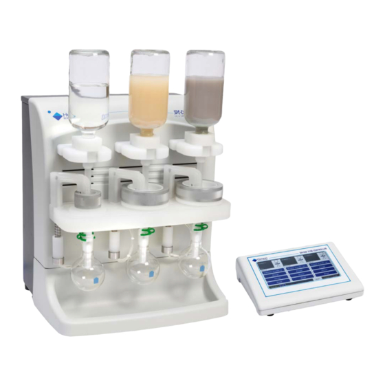
Overview You should be completely familiar with all parts and functions of the SPE-DEX 3100 System be- fore you start to use it. This section provides an overview of Extractor and Controller features. SPE-DEX 3100 Oil & Grease Extractor Sample Bottle... - Page 29 Figure 4-2. Detail of the Collection Vessel Area The major components on the front of the Oil & Grease Extractor System are: Holds sample to be used with the SPE-DEX 3100 Extractor. The Sample Bottle Extractor is designed to accommodate a standard round sample bottle with narrow neck of 1-L capacity with 33 x 400 mm threads (also known as a Boston Round).
- Page 30 Line Fitting Water Waste Line Fitting Figure 4-3. Rear of the SPE-DEX 3100 System The major components on the rear of the Oil & Grease Extractor System are: Connects the Extractor to the 3100 Controller, which provides Controller Data Port both power and communication.
-
Page 31: Spe-Dex 3100 Controller
SPE-DEX 3100 Controller Touch Screen Figure 4-4. Front of the SPE-DEX 3100 Controller The major component on the front of the SPE-DEX 3100 Controller is: Displays all system parameters and operating status. The touch screen is the Touch Screen user interface for method programming and system inputs. - Page 32 Power Switch Ethernet Port Figure 4-6. Rear of the SPE-DEX 3100 Controller The major components on the rear of the SPE-DEX 3100 Controller are: Power Switch Turns the SPE-DEX 3100 System on/off. Connects the 3100 Controller to a 120 or 240 Volt AC power source via a Power Input 15 VDC supply.
- Page 33 4.2: SPE-DEX 3100 Controller Notes:...
-
Page 34: Spe-Dex 3100 System Installation
System Installation Procedure Step 1: With the SPE-DEX 3100 System in the area where it will be used, temporarily position the Sys- tem at an angle to allow easy access to the rear connection fittings from the side. Step 2: Locate the solvent delivery system canisters and place them near the Extractor. - Page 35 Figure 5-2. Grounding Wire Attached to a Safe Ground Step 4: Canister labels are provided with the SPE-DEX 3100 System: Note: Solvent 1 may be n-hexane or petroleum ether. Solvent 2 is always methanol. Place the appropriate label on each canister.
- Page 36 5: SPE-DEX 3100 System Installation Figure 5-3. Canister Labels Step 5: Figure 5-4 shows the gas valves in the open and closed positions. To vent the gas pressure before filling the solvent, close the valve to the source and open the unconnected vent port valve.
- Page 37 5.1: Installing the SPE-DEX 3100 System Important! Be careful not to twist the solvent line when tightening the fitting. This could kink the line. Connections Figure 5-5. Solvent Line Connection on the Canister Connect the clear tubing on the other end of the solvent line bundle to the brass bulkhead fit- ting labelled HEXANE (Figure 5-6).
- Page 38 60 psi. (This must be inert gas, such as nitrogen, to limit flamma- bility hazard. Compressed air is not recommended or acceptable). Figure 5-7. SPE-DEX 3100 System Connections Step 10: Fill the canisters, as described in the steps below.
- Page 39 5.1: Installing the SPE-DEX 3100 System Figure 5-8. Unclamping the Lid to the Canister Fill the canister labeled Solvent 1 (n-hexane) with n-hexane (85% purity, 99.0% min. saturat- ed C isomers, and residue less than 1 mg/L). Fill the canister to a level just below the bottom of the neck.
- Page 40 5: SPE-DEX 3100 System Installation Caution: A high vacuum is applied to the solvent recovery bottle. DO NOT SUBSTITUTE any other container. Structural failures can occur if other containers are used. Step 13: Locate the clear solvent waste line previously attached to the Extractor. If desired, cut the line to the necessary length.
- Page 41 5.1: Installing the SPE-DEX 3100 System waste recovery assembly mounted on the solvent recovery bottle (Figure 5-12). Using a T-fitting, connect the other end of the tubing to the top elbow fitting on the water waste recovery assembly (Figure 5-13).
- Page 42 Note: It is strongly recommended to have a vacuum gauge on the main vacuum in order to moni- tor the vacuum level and ensure that the proper vacuum is maintained. This completes the installation of the SPE-DEX 3100 System.
-
Page 43: Initial System Verification
5.2: Initial System Verification The vacuum pump/source, power, and pressurized gas source should be turned off when the Ex- tractor is not in use. Initial System Verification Step 1: Set up for operation, as described in Section 7.1, page 39. Complete the entire procedure, follow- ing the steps for Verification. - Page 44 5: SPE-DEX 3100 System Installation Step 3: Run the Verification method by completing the procedure in Section 7.3, Running a Method, page 45. Step 4: Verify the operation of each step using the table below. Repeat all steps for each station. Place a check in each box as you see the extractor performing this step or observe the step on the status page of the controller.
-
Page 45: Operation Overview
Operation Overview The SPE-DEX 3100 System automates the extraction of oil and grease from aqueous samples by using Solid Phase Extraction (SPE) disks. Solid phase extraction is a process that can be used to retain the analytes of interest, allowing the solvent to be exchanged or interferences to be re- moved. -
Page 46: Step 1: Conditioning
6: Operation Overview Elute: solvent is pulled through the disk and delivered (eluted) to the collection vessel Each method step is described in more detail below. Step 1: Conditioning This step pre-wets and conditions the SPE disk with solvents. The Conditioning steps of a method prepare the SPE disk to receive the water sample. The first conditioning solvent, n-hexane, removes any potential interferences from the disk. -
Page 47: Step 3: Air Dry
6.3: Step 3: Air Dry Step 3: Air Dry This step air dries the SPE Disk to remove residual water. When the water sample has been completely filtered, the liquid level sensor is exposed to air and undergoes a change in temperature (warms up). The Extractor station then advances into the Air Dry step for the programmed duration. - Page 48 6: Operation Overview Notes:...
-
Page 49: Operation Procedures
Operation Procedures The procedures described in this section are: • Setting Up for Operation, Section 7.1, below • Loading the SPE Disk, Section 7.2, page 45 • Running a Method, Section 7.3, page 45 • Running a Practice Method, Section 7.4, page 48 •... - Page 50 7-1). Figure 7-1. Check Valve Opening The SPE-DEX 3100 System uses a single HPLC grade check valve assembly. This assembly is used to prevent fluids from dripping into the collection vessel from the Disk Holder. While this check valve prevents leaks, the highly polished surface can cause the internal components to stick if not used routinely.
- Page 51 Then, attach the water sample inlet valve assembly to the adapter. Note: Cap adapters for various bottle sizes are available through Horizon Technology. To ensure that the appropriate cap adapters are obtained, determine either the dimensions of the threading...
- Page 52 7: Operation Procedures Step 11: Remove the cap from the sample bottle if one is in place. Inspect the condition of the bottle rim and threads and ensure that there are not chips or significant defects. Carefully thread the water sample inlet valve onto the sample bottle.
- Page 53 7.1: Setting Up for Operation Figure 7-7. Attach a Water Sample Inlet Valve with Bottle to the System Step 14: Be sure the sample bottle rests firmly in the water sample holder arm, using a pinching motion to tighten it. Figure 7-8.
- Page 54 7: Operation Procedures Clip Collection Vessel Figure 7-9. Attach the Collection Vessel and Retaining Clip Step 17: If you are using a WaterTrap drying membrane with the system firmly fit it to the tip of the port where the collection vessel attaches (Figure 7-10). It may be necessary to attach the WaterTrap at the same time as preparing to attach the collection vessel if the space is tight.
-
Page 55: Loading The Spe Disk
7.2: Loading the SPE Disk Loading the SPE Disk Step 1: Place the metal SPE disk support screen (1.450”) into the center of the 47- mm disk holder cup. If using the 100-mm disk holder cup, use the larger (3.150”) diameter support screen. Make sure the screen sits within the recess in the disk holder (Figure 7-11) as flatly as possible. -
Page 56: Running A Verification, Practice, Or Standard Factory Method
7.3.1 Running a Verification, Practice, or Standard Factory Method Step 1: After the SPE-DEX 3100 System is set up for operation, as described in Section 7.1 (page 39), you are ready to run a method. Step 2: Select a method by pressing the selected Method button. - Page 57 7.3: Running a Method After reviewing, press Cancel and then either Load Method or Load to All Stations to continue running the selected method. Load Method To load the selected method so that it will run on the selected station. Load to All Stations To load the selected method so that it will run on all stations.
-
Page 58: Running A Practice Method
Running a Practice Method To gain familiarity with running the SPE-DEX 3100 Oil & Grease Extractor with a water sample, it is recommended to begin by using a Practice method you have created and run yourself. This Practice method will enable you to observe and understand the operation of the SPE-DEX 3100 System. -
Page 59: Purge Method Overview
7.6: Running a Purge Method • Remove any air in the solvent lines prior to running any samples, typically performed after physically refilling the solvent canisters. • Confirm that, during the initial system installation, all of the solvent solenoid valves are func- tioning properly. -
Page 60: Procedure To Run A Purge Method
The spray should hit the center of the base of the bottle and uniformly wash down the in- side walls. If the spray is not uniform, contact Horizon Technology. Note: Until all of the air has been removed from the rinse solvent lines, minimal and inconsistent volumes of solvent will be collected. - Page 61 7.7: Shutting Down the System Step 5: Repeat Steps 1 through 3 for all stations. Step 6: Turn off the vacuum. Step 7: Remove the cap from the 5-gallon water waste plug assembly to vent the system. Replace the cap when the pressure has been released.
-
Page 62: 3100 Controller Features
3100 Controller Features Overview The 3100 Controller provides the user interface to the SPE-DEX 3100 System stations. This sec- tion provides an overview of the 3100 Controller unit and extraction methods. This information is followed by the features provided on the System page. -
Page 63: System Page
System Page Figure 8-2. System Page 8.1.4 Guide Page The Guide page provides an overview of the steps to operate the SPE-DEX 3100 System: • Prepare system checklist • Run a sample • Shutdown the SPE-DEX 3100 System Figure 8-3. Guide Page... - Page 64 8: 3100 Controller Features The Guide is a checklist reference for basic system operation and oil and grease extraction. Key steps have links to operational menus or descriptive text tips, or images to help the inexperienced or infrequent user with basic operations. Information is presented in three ways: Figure 8-4.
-
Page 65: Extraction Methods
8.1.5 Extraction Methods The SPE-DEX 3100 Controller can store more than thirty (30) operator-created custom oil and grease extraction methods. Eight (8) factory chemistry methods and two (2) system methods are factory preset and cannot be modified or deleted, though they can be edited and saved as opera- tor-created custom methods. -
Page 66: Viewing And Loading A Method
8: 3100 Controller Features Running a method is described in Section 7.3, page 45. Viewing and Loading a Method 8.3.1 Viewing a Method Step 1: Press the Selected Method button on the Home screen. The Select Method page is displayed. For example: Figure 8-5. -
Page 67: Loading The Same Method To All Stations
8.4: Editing an Existing Method or Creating a New Method Step 2: Select a method on the list. Step 3: Press the Load Method button. The method is loaded to the station and displayed on the Home page. 8.3.3 Loading the Same Method to All Stations Step 1: On the Home screen, press the Selected Method button for any of the station. - Page 68 8: 3100 Controller Features Figure 8-8. Name for the New Method Dialog Press the field labeled, Enter a New Name for the Method. A keypad is displayed: Figure 8-9. Keypad Use the keypad to enter a name for the new method. Press Enter. The name is displayed in the Name for the New Method dialog: Figure 8-10.
- Page 69 8.4: Editing an Existing Method or Creating a New Method • Step 1: Condition 1 (n-hexane) • Step 2: Condition 2 (methanol) • Step 3: Load Sample • Step 4: Air Dry • Step 5: Rinse, etc. (this step is available with several options) Use the scroll bar on the right to review the entire method.
- Page 70 8: 3100 Controller Features Saturate Allows a small amount of the methanol to be pulled into the pore spaces of the SPE disk to soak and clean the sorbent bed inside of the SPE disk. Typical times are between 1 and 2 seconds. The maximum time typically should be 60 seconds.
-
Page 71: Deleting A Method
8.5: Deleting a Method Wash MeOH Sprays methanol into the sample bottle. A rinse time of 2 seconds is recom- mended if using a 47-mm SPE disk and 4 seconds if using a 100-mm SPE disk. Saturate Sets the saturate time. A saturate of 1 second is typical. Soak Sets the soak time for the second step. - Page 72 8: 3100 Controller Features Solvent levels are indicated at the bottom left of the Home page. For example: The Solvent 1 canister is almost full and the Solvent 2 canister is low. The Solvent 1 canister contains less than 10% and the Solvent 2 canister is low. You can check solvent levels at any time via the Solvent Levels feature on the System tab or simply by pressing on the images shown above to go to the Solvent Levels page (described be- low).
-
Page 73: Setting Sounds
8.6: Using Additional System Options Figure 8-14. Check Solvent Levels Page Step 2: You can turn the Solvent Monitor on or off. If it is turned off you will not get a warning when the solvent level is low. This is password restricted. Step 3: After physically refilling the solvents (typically at the daily system startup), the solvent monitor levels should be reset/refilled to keep estimated solvent calculations accurate. -
Page 74: Reviewing Raw A2D Values
8: 3100 Controller Features Figure 8-16. System - Sounds Page Step 2: For each type of sound, press the selection list and select an option. Step 3: Press OK to return to the System page. 8.6.3 Reviewing Raw A2D Values This section is intended for troubleshooting and is not typically accessed. -
Page 75: Setting A Password
8.6: Using Additional System Options The 3100 Controller has the capability of counting the total number of samples processed on each station and the total number of hours of run time. Hours since the last reset and a total sample run time is also displayed on a splash screen to help indicate when service is needed. -
Page 76: Defining Sample Settings
8: 3100 Controller Features Figure 8-20. Password Settings Page Step 4: Press Ok to return to the System page. If the password is lost, contact Horizon Technology to have it reset. Note: The default password is 1234. This is available until changed. -
Page 77: Updating Software
To update software, insert a USB flash drive with the provided update into the USB port on the back of the 3100 Controller. USB Port Figure 8-22. Rear of the SPE-DEX 3100 Controller Step 2: From the System tab, select Update and follow the screen prompts to reboot the system. -
Page 78: Setting Screen Brightness
8: 3100 Controller Features Figure 8-24. Update Error 8.6.8 Setting Screen Brightness You can adjust the brightness of the touch screen. Step 1: On the System page, press the Screen button. The Screen Settings page is displayed: Figure 8-25. Screen Settings Page Step 2: Move the slider to set your brightness preference. -
Page 79: Restoring Defaults
8.6: Using Additional System Options Figure 8-27. System Test Page Step 3: Press OK at the end of the test to return to the System page. 8.6.10 Restoring Defaults This feature reloads the factory settings, leaving any created methods intact. This option is pass- word restricted. - Page 80 8: 3100 Controller Features Notes:...
-
Page 81: Part Ii: Maintenance And Troubleshooting
Part II: Maintenance and Troubleshooting... -
Page 82: Maintenance
Horizon Technology, Inc. for assistance. Freeing the Elute Check Valve Assembly The SPE-DEX 3100 Oil & Grease Extractor uses a single HPLC-grade check valve assembly for each extractor station. This assembly is used to prevent solvent or the water sample from dripping into the collection vessel during the Soak and Process Sample steps or while the system is paused. -
Page 83: Cleaning The Water Sample Inlet Valve Assembly
9.2: Cleaning the Water Sample Inlet Valve Assembly Cleaning the Water Sample Inlet Valve Assembly The water sample inlet valve, (Figure 9-3) is the delivery mechanism by which the sample is dis- pensed onto the Solid Phase Extraction (SPE) disk. A nitrogen actuator automatically controls the opening and closing of the ball valve design. -
Page 84: Replacement Of O-Rings
2872 includes this tool, instructions, and new solvent rods with o-rings. Step 3: Run the Purge method again. If leaking continues, contact a Horizon Technology representative. Sample Bottle Gasket Seals Please follow the instructions below when replacing the sample bottle gasket seal on the water sample inlet valves. -
Page 85: Replacing The Disk Holder Cup O-Ring
9.5: Replacing the Disk Holder Cup O-ring could result in leaks between the surfaces. When leaks do occur, the sample overflow sensor may trip, pausing the run until the issue is resolved. Inspect the Sample Bottle Gasket Seal Step 1: Remove the sample bottle gasket from the water sample inlet valve. -
Page 86: Assembly Of The Dual Diaphragm Oil-Free Vacuum Pump
Figure 9-7. O-Ring Assembly of the Dual Diaphragm Oil-Free Vacuum Pump The dual diaphragm oil-free vacuum pump offers several advantages over other vacuum pumps. The most noticeable advantage is seen when using 100-mm SPE Disks. The dual diaphragm pump is capable of maintaining adequate vacuum levels under the increased draw from larger SPE disks in an air dry step. -
Page 87: Cleaning And Replacing The Elute Check Valve
9.7: Cleaning and Replacing the Elute Check Valve Step 4: Connect the vacuum gauge provided with the system to the “T” fitting. Step 5: On the discharge side of the vacuum pump, install the brass plug in one of the openings and the compression fitting in the other. - Page 88 Notes:...
-
Page 89: Troubleshooting
Troubleshooting The SPE-DEX 3100 Oil & Grease Extractor is engineered to perform in a demanding environ- ment. This system is a mixture of electrical, mechanical, and pneumatic subsystems. Unfamiliari- ty with the operation of the system, especially with new system start-ups, can be intimidating. - Page 90 10: Troubleshooting • Check for liquid leaks. Conditioning solvent overflows • Verify the dispense time programmed for the 3100 Controller method. • With the unit sitting idle and solvent canisters pressurized, verify that solvent does not leak from the prewet/conditioning arm. A leak would indicate a stuck open conditioning valve. •...
- Page 91 10.1: Troubleshooting Tips • The two halves of the water inlet valve assembly should be tight enough so that sample does not overflow. If too tight, the water inlet valve will not open. Also verify that the down tube that drains the sample into the disk holder assembly is snug in place. Sample is not draining to waste or is draining very slowly •...
- Page 92 10: Troubleshooting Rinse leak from rinse port • The solvent rod o-rings are susceptible to damage with prolonged exposure to the solvents. If a rinse leak is occurring during the rinse spray step, the solvent rod o-rings need to be re- placed.
- Page 93 10.1: Troubleshooting Tips • Program a short method with only the n-hexane rinse solvent and set all other parameters to zero. Set the dispense time so that approximately 30 mL of solvent is collected. Set the soak time to zero and drain time to 10 seconds. Use the 100-mm Disk Holder Assembly with no disk.
- Page 94 10: Troubleshooting Notes:...
-
Page 95: Part Iii: Appendices
Part III: Appendices... -
Page 96: Preprogrammed Methods
Preprogrammed Methods The following methods are included in the 3100 Controller. 100 mm Pacific Saturate Drain No Prefilter V2 Dispense Rinse Saturate Elute Soak Solvent Elute Condition 1 Step 1: 10 s 30 s 60 s Hexane Step 2: Condition 2 10 s 30 s Methanol... - Page 97 47 mm Pacific Saturate Drain no Prefilter V2 Dispense Rinse Saturate Elute Soak Solvent Elute Step 1: Condition 1 30 s 30 s Hexane Step 2: Condition 2 30 s 30 s Methanol Step 3: Load Sample Load is controlled automatically by the sensors. Step 4: Air Dry 180 s...
- Page 98 47 mm Trap V2 Saturate Drain Dispense Rinse Saturate Elute Soak Solvent Elute Condition 1 Step 1: 30 s 60 s Hexane Step 2: Condition 2 Methanol Step 3: Load Sample Load is controlled automatically by the sensors. Step 4: Air Dry 480 s Step 5:...
- Page 99 47 mm Trap Saturate Drain Premium V2 Dispense Rinse Saturate Elute Soak Solvent Elute Step 1: Condition 1 30 s 60 s Hexane Condition 2 Step 2: Methanol Step 3: Load Sample Load is controlled automatically by the sensors. Step 4: Air Dry 480 s Step 5:...
- Page 100 100 mm Trap V2 Saturate Drain Dispense Rinse Saturate Elute Soak Solvent Elute Step 1: Condition 1 10 s 30 s 60 s Hexane Condition 2 Step 2: Methanol Step 3: Load Sample Load is controlled automatically by the sensors. Step 4: Air Dry 480 s...
- Page 101 Clean System Step 1: Drain Sample Step 2: Drain Solvent Step 3: Elute Step 4: Rinse Method Step 5: Drain Sample Step 6: Drain Solvent Step 7: Elute Step 8: Rinse Hexane Step 9: Drain Sample Step 10: Drain Solvent Step 11: Elute Drain...
- Page 102 Method Worksheet 16 Northwestern Drive, Salem, NH 03079 Telephone: (603) 893-3663 Toll-Free: (800) 997-2997 USA only Website: www.horizontechinc.com Method Name: ___________________________________________________________ Drain Dispense Saturate Soak Solvent Step 1: Condition Hexane (Solvent 1) Step 2: Condition Methanol (Solvent 2) Step 3: Load Sample Load is controlled automatically by the sensors.
-
Page 103: Parts List
Parts List The following items are necessary to run the SPE-DEX 3100 Oil & Grease Extractor : • Water Sample Inlet Valves (3) • Liquid Handling Kit • Solvent Delivery System for dispensing n-hexane (1) and methanol (1) • Water Waste Recovery Assembly (including a 20-L waste water recovery bottle) •... -
Page 104: Bottle Cap Adapters For The Spe-Dex 3100 Extractor
Bottle Cap Adapters for the SPE-DEX 3100 Extractor The water sample inlet valves for the SPE-DEX 3100 Oil & Grease Extractor are designed to fit a 33x400 narrow-mouth bottle (Boston round bottle). If a larger sample bottle will be used, select the bottle cap adapter that will fit your sample bottles. -
Page 105: Vacuum Requirements
Vacuum Requirements Part Number Description 50-2480-01 GAST Vacuum Pump w/ Plumbing Kit -- Model DAA-V716-EB (120V60HZ 50-2480-02 GAST 220V 50/60HZ VAC PMP PLUMBED (220V60HZ). - Page 106 Notes:...
-
Page 107: Spe-Dex 3100 System Setup
SPE-DEX 3100 System Setup... -
Page 109: Warranty
Warranty Limited Warranty Horizon Technology, Inc. (“Horizon”) warranties the SPE-DEX 3100 Oil & Grease Extractor (Product) against defects in material or workmanship as follows: 1. LABOR: For a period of one (1) year from the date of purchase, if this Product is determined to be defective, Horizon will repair the Product, and will cover all labor charges. - Page 110 Notes:...
Need help?
Do you have a question about the SPE-DEX 3100 and is the answer not in the manual?
Questions and answers