
Summary of Contents for Controlled power company MODEL ES
- Page 1 TROY, MICHIGAN MODEL ES OWNERS MANUAL 4.5KVA - 15.5KVA UNINTERRUPTIBLE POWER SUPPLY IMPORTANT - SAVE THESE INSTRUCTIONS - PLEASE READ THIS MANUAL BEFORE USING EQUIPMENT 112259 - Rev 20 08/24/2020...
- Page 2 The following symbol indicates that caution should be taken when performing the process required in this manual. Damage to the unit or personal harm could hap- pen if proper precautions are not taken. Caution The following symbol indicates that there is a risk of electrical shock if proper precautions are not followed.
-
Page 3: Table Of Contents
TABLE OF CONTENTS INTRODUCTION ...................4 RECEIVING THE UPS ................6 INSTALLATION PRECAUTIONS ............8 PRELIMINARY INSTALLATION ............9 INSTALLATION ...................14 CHANGING THE INPUT VOLTAGE ............18 DIP SWITCH SET UP................22 COMMUNICATIONS DESCRIPTION ..........23 OPTIONAL REMOTE ANNUNCIATOR INSTALLATION ..... 24 OPTIONAL REMOTE COMMUNICATIONS ........26 OPTION INTERCONNECTION DIAGRAM .........27 START UP PROCEDURE ..............28 OPERATION ..................29 MAINTENANCE PROCEDURES ............43... -
Page 4: Introduction
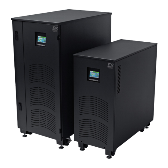
True Online Double Conversion With Static Bypass The “Model ES” is a true on-line double conversion UPS. AC input power is converted to DC power to keep system batteries charged, then converted back to AC power to feed your mission critical equipment. Because the double conversion system reproduces its own regulated sinewave output, your equipment is no longer at the mercy of the input voltage distortions, frequency variations, voltage sags, surges, under-voltages, and power failures. - Page 5 Input Power Factor Correction With Less Than 5% THD The “Model ES” goes beyond a traditional double conversion UPS. The advanced bi-directional input power fac- tor correction circuitry and independently-generated sine wave reference, guarantee that the input current is free of harmonics regardless of input voltage distortion.
-
Page 6: Receiving The Ups
RECEIVING THE UPS INSPECTION, PLACEMENT, INSTALLATION, SETUP AND START-UP SHOULD BE PERFORMED BY QUALIFIED PERSONNEL ONLY INSPECTION Upon receipt of the UPS, visually inspect the unit(s) for shipping damage. If shipping damage has occurred, the purchaser should promptly notify the carrier and file a claim with the carrier. The factory should be notified if the damages may impair the operation of the unit. - Page 7 RECEIVING THE UPS CONTINUED REMOVING THE UPS FROM THE PALLET ***CAUTION*** CABINETS AND BATTERIES ARE EXTREMELY HEAVY USE PROPER EQUIPMENT WHEN REMOVING THE CABINETS FROM THE SKID *****SHOCK HAZARD***** DO NOT SHORT BATTERY TERMINALS TOOLS REQUIRED: 1/2” Socket, Forklift, dolly. 1.
-
Page 8: Installation Precautions
INSTALLATION PRECAUTIONS IMPORTANT SAFEGUARDS, READ AND FOLLOW ALL SAFETY INSTRUCTIONS. SAVE THESE INSTRUCTIONS. ***** CAUTION ***** A BATTERY CAN PRESENT A RISK OF ELECTRICAL SHOCK AND HIGH SHORT CIRCUIT CURRENT. THE FOLLOWING PRECAUTIONS SHOULD BE OBSERVED WHEN WORKING ON BATTERIES: •... -
Page 9: Preliminary Installation
PRELIMINARY INSTALLATION TOOLS REQUIRED AND INSTALLATION CHECKLIST ***** CAUTION ***** To reduce risk of fire, connect only to maximum input current rated, branch circuit overcurrent protection (see input breaker from table below) in accordance with National Electrical Code, ANSI/NFPA 70.” This unit is intended for installation in a temperature controlled, indoor area free of conductive contaminants. - Page 10 PRELIMINARY INSTALLATION CONTINUED AC OUTPUT CURRENT MATRIX This unit is intended for installation in a temperature controlled, indoor area free of conductive contaminants. OUTPUT MATRIX (KVA) 4.5 KVA 5.5 KVA 6.5 KVA 7.5KVA 8.3 KVA 9.0 KVA OUTPUT OUTPUT OUTPUT OUTPUT OUTPUT OUTPUT...
- Page 11 PRELIMINARY INSTALLATION CONTINUED 4.5 KVA - 11.0 KVA, “S” CABINET WITH INTERNAL BATTERIES CABINET DIMENSIONS AND CLEARANCES This unit is intended for installation in a temperature controlled, indoor area free of conductive contaminants. UPS PLACEMENT Refer to the drawing below for installation clearances and ventilation requirements. The UPS should be placed in a dry, well ventilated or temperature controlled area.
- Page 12 PRELIMINARY INSTALLATION CONTINUED 4.5 KVA - 15.5 KVA, “T” CABINET WITH INTERNAL BATTERIES CABINET DIMENSIONS AND CLEARANCES This unit is intended for installation in a temperature controlled, indoor area free of conductive contaminants. UPS PLACEMENT Refer to the drawing below for installation clearances and ventilation requirements. The UPS should be placed in a dry, well ventilated or temperature controlled area.
- Page 13 PRELIMINARY INSTALLATION CONTINUED 4.5 KVA - 15.5 KVA, “T” CABINET WITH EXTERNAL BATTERIES CABINET DIMENSIONS AND CLEARANCES This unit is intended for installation in a temperature controlled, indoor area free of conductive contaminants. UPS PLACEMENT Refer to the drawing below for installation clearances and ventilation requirements. The UPS should be placed in a dry, well ventilated or temperature controlled area.
-
Page 14: Installation
INSTALLATION INPUT AND OUTPUT CONDUIT ENTRY POINTS AND TERMINAL LOCATIONS *** WARNING *** RISK OF ELECTRICAL SHOCK THE UPS RECEIVES POWER FROM MORE THAN ONE SOURCE. BE SURE ALL UTILITY CIRCUIT BREAKERS ARE IN THE OFF POSITION AND THE BATTERY CONNECTOR IS UNPLUGGED BEFORE INSTALLATION OR SERVICING. “S”... - Page 15 INSTALLATION CONTINUED INPUT WIRING *** WARNING *** RISK OF ELECTRICAL SHOCK THE UPS RECEIVES POWER FROM MORE THAN ONE SOURCE. BE SURE ALL UTILITY CIRCUIT BREAKERS ARE IN THE OFF POSITION AND THE BATTERY CONNECTOR IS UNPLUGGED BEFORE INSTALLATION OR SERVICING. Input Wiring Input wiring is performed at the input terminal block.
- Page 16 INSTALLATION CONTINUED OUTPUT WIRING - “S” CABINET Output Wiring Output wiring is performed at the output terminal block or at the load side (bottom) of the optional distribution break- ers on the rear panel or plugged in directly to the optional output receptacles. See Illustration below. It is recom- mended that all wiring is performed according to NEC standards and local codes.
- Page 17 INSTALLATION CONTINUED OUTPUT WIRING - “T” CABINET Output Wiring Output wiring is performed at the output terminal block or at the load side (bottom) of the optional distribution break- ers on the rear panel or plugged in directly to the optional output receptacles. See Illustration below. It is recom- mended that all wiring is performed according to NEC standards and local codes.
-
Page 18: Changing The Input Voltage
CHANGING THE INPUT VOLTAGE AVAILABLE ONLY ON THE LARGE “T” CABINET - 4.5 - 15.5KVA ***** WARNING ***** RISK OF ELECTRICAL SHOCK THE UPS RECEIVES POWER FROM MORE THAN ONE SOURCE. BE SURE ALL UTILITY CIRCUIT BREAKERS ARE IN THE OFF POSITION AND THE BATTERY CONNECTOR IS UNPLUGGED BEFORE INSTALLATION OR SERVICING. - Page 19 CHANGING THE INPUT VOLTAGE CONTINUED STEP 2 - SET MONITOR PARAMETERS ***** CAUTION ***** THE FOLLOWING PROCEDURE MUST BE FOLLOWED EXACTLY. DO NOT ALTER ANY OTHER PARAMETERS. THE PASSWORD GIVEN ALLOWS YOU TO MODIFY ALL FACTORY SETTINGS AND SHOULD BE KEPT FROM UNAUTHORIZED PERSONEL. 1.
- Page 20 CHANGING THE INPUT VOLTAGE CONTINUED STEP 3 - SETTING INTERNAL PARAMETERS (SYSTEM MEMORY MODIFICATION) ***** CAUTION ***** THE FOLLOWING PROCEDURE MUST BE FOLLOWED EXACTLY. DO NOT ALTER ANY OTHER PARAMETERS. Tools required: USB Cable with a type “B” plug, Computer (Windows XP or Vista operating systems only), USB Installation CD and instructions (on CD).
- Page 21 CHANGING THE INPUT VOLTAGE CONTINUED Once communication has been established, type “mm” (System Memory Modification). Hit the “escape” key to scroll to the desired parameter to be changed, in this case stop when you get to “Module-Input Nominal L1-L2”. There are two parameters that need to be changed under the “Module-Input Nominal L1-L2” parameter.
-
Page 22: Dip Switch Set Up
DIP SWITCH SET UP SETTING THE DIP SWITCHES (SW1) SW1 Dip Switch Settings (located on the rear panel near the top left - see below). Switch #1 - For restart options, set this dip switch to one of the following positions. OPEN = Manual restart required. -
Page 23: Communications Description
COMMUNICATIONS DESCRIPTION ALARM TERMINAL DESCRIPTION FOR 125VAC DISCREET WIRING SCENARIOS Eleven (11) position contact closure terminal. Provides R.E.P.O., Test Active, General Alarm, Low Battery and On Battery. Note: User selectable, Normally open or closed, Dry contacts rated: 125VAC @ 0.5 Amps. REAR VIEW OF INVERTER CABINET USB PORT (FOR SERVICE SW1 DIP SWITCHES... -
Page 24: Optional Remote Annunciator Installation
Turn off all power before installing or servicing! REMOTE ANNUNCIATOR Controlled Power Company’s Remote Annunciator is capable of displaying status conditions of an Uninterruptible Power Supply and alarming under critical conditions. The following installation instructions include operation, wir- ing, and mounting your Remote Annunciator. - Page 25 OPTIONAL REMOTE ANNUNCIATOR INSTALLATION 120VAC POWER, 50/60Hz TO REMOTE ANNUNCIATOR CABLE. 2 WIRE W/ GROUND TERMINAL SUPPLIED BY OTHER L1 - 120V - BLACK TO UPS N - WHITE OUTPUT - 120V GROUND - GREEN (BARE) NOT USED - BLACK SHIELD WIRE (BARE) NOT USED - BROWN + 12v - WHITE...
-
Page 26: Optional Remote Communications
NETMINDER REMOTE COMMUNICATIONS NetMinder Slot Card The NetMinder Slot Card integrates the “Model ES” into an Ethernet TCP/IP, MODBUS TCP, or MODBUS RS485 network with a specific IP address. The NetMinder offers you remote monitoring of the UPS status, battery test pass/fail results, alarm conditions, and electrical measurements via a web browser, without the need for any external software. -
Page 27: Option Interconnection Diagram
OPTION INTERCONNECTION DIAGRAM TO ETHERNET “T” CABINET TERMINAL ORIENTATION REAR VIEW OF INVERTER CABINET NETMINDER ADAPTER (Internal to System) (See NetMinder quick start guide for set up instructions). TO K6 PINS 1 - 2 “T” CABINET REAR VIEW OF INVERTER CABINET “S”... -
Page 28: Start Up Procedure
START UP PROCEDURE DO NOT ATTEMPT TO OPERATE THE UNIT UNTIL ALL SET UP PROCEDURES HAVE BEEN COMPLETED CAUTION - DO NOT PLACE UNIT IN BYPASS WHILE BATTERY TESTING IS IN PROGRESS. 1. Turn off all AC input and output circuit breakers. Verify that there are not any shorts on the input and output cables. 2. -
Page 29: Operation
OPERATION INTELLISTAT TS MONITOR DESCRIPTION ADVANCED DIGITAL MONITORING - The user-friendly Intellistat TS monitor provides quick, full access to all of the monitor features, and also allows all programming to be done directly from the monitor. An easy to read LCD indicates all the electrical parameters, as well as the functional status of the inverter. - Page 30 OPERATION CONTINUED INTELLISTAT TS MONITOR OPERATION MONITOR TREE *** CAUTION *** IT IS RECOMMENDED THAT ALL PARAMETERS BE LEFT AT FACTORY PRESET LEVELS. IF MODIFICATION OF SYSTEM PARAMETERS AND ALARM LEVELS IS REQUIRED PLEASE CONTACT THE FACTORY PRIOR TO MODIFICATION. IMPROPERLY SETTING ALARM LEVELS MAY RESULT IN NUISANCE ALARMS.
- Page 31 OPERATION CONTINUED INTELLISTAT TS MONITOR OPERATION PARAMETER DEFINITIONS TIME: 07:58:17 AM SYSTEM NORMAL DATE: 03/31/10 MANUAL BYPASS STATIC BYPASS LOAD % INVERTER LINK INPUT OUTPUT BATTERY BATTERY STATUS CHARGE PARAM ALARMS SETUP TEST ON/OFF PARAMETERS MENU SUB MENU MEANS TERM PARAMETERS INPUT INPUT VOLTAGE FROM L1 TO L2...
- Page 32 OPERATION CONTINUED INTELLISTAT TS MONITOR OPERATION PARAMETER DEFINITIONS PARAMETERS MENU SUB MENU MEANS TERM SETUP HIGH HIGH OUTPUT VOLTAGE X1 TO N ALARM LEVEL AC VOLTS X1-N HIGH OUTPUT VOLTAGE X2 TO N ALARM LEVEL AC VOLTS X2-N HIGH VA X1 TO N ALARM LEVEL VA X1-N HIGH VA X2 TO N ALARM LEVEL VA X2-N...
- Page 33 OPERATION CONTINUED INTELLISTAT TS MONITOR OPERATION This section will give you a basic understanding of the Intellistat TS Monitor, its menu items and functions. All parameters are preset at the factory. GENERAL - The system is pre-programmed at the factory specific to your unit. There should be no need to change any system parameters.
- Page 34 OPERATION CONTINUED INTELLISTAT TS MONITOR OPERATION COMMON SCREENS PASSWORD SCREENS Passwords are required to access certain screens. A typical password screen is shown below. Enter the desired number using the key pad. The number selected will appear next to the “Enter Password” area. When the numbers desired are fully entered, select “ENT”...
- Page 35 OPERATION CONTINUED INTELLISTAT TS MONITOR OPERATION MAIN SCREEN Typical “System Normal” Main Screen showing TIME: 07:58:17 AM SYSTEM NORMAL the percentage load for each output and the DATE: 03/31/10 battery charge level. The Low Battery and output overload indicators will change to red if the levels MANUAL BYPASS reach the programmed set points (factory set) STATIC BYPASS...
- Page 36 OPERATION CONTINUED INTELLISTAT TS MONITOR OPERATION TYPICAL BYPASS SCREENS MAIN SCREEN - ON STATIC BYPASS TIME: 07:58:17 AM ON STATIC BYPASS DATE: 03/31/10 The screen will return to the Typical ON STATIC BYPASS SYSTEM NORMAL screen screen. There is no alarm MANUAL BYPASS when the bypass condition indication or logging with this...
- Page 37 OPERATION CONTINUED INTELLISTAT TS MONITOR OPERATION MANUAL BATTERY TESTING Default customer password = 05151 TIME: 07:58:00 AM SYSTEM NORMAL DATE: 04/16/10 Press the “TEST” button to invoke a MANUAL BATTERY TEST battery test (Duration = 30 Seconds). The duration is preset at the factory TEST DURATION and is not user accessible.
- Page 38 OPERATION CONTINUED INTELLISTAT TS MONITOR OPERATION PERIODIC BATTERY TESTING Default customer password = 05151 Push to enable the test. P r e s s t h e “ T E S T ” Factory preset disabled. b u t t o n t o i n v o k e a TIME: 07:58:00 AM The test will auto run SYSTEM NORMAL...
- Page 39 OPERATION CONTINUED INTELLISTAT TS MONITOR OPERATION ANNUAL BATTERY TESTING Default customer password = 05151 Push to enable the P r e s s t h e “ T E S T ” test on a yearly basis. b u t t o n t o i n v o k e a TIME: 07:58:00 AM SYSTEM NORMAL Factory preset disabled.
- Page 40 OPERATION CONTINUED INTELLISTAT TS MONITOR OPERATION ALARMS, ALARM LOGS AND TEST LOGS TYPICAL ALARM SCREEN PUSH TO PUSH TO PUSH TO TIME: 07:58:17 AM TOTAL ALARM: 01 SILENCE DATE: 04/16/10 SILENCE ! SILENCE ! AC OUTPUT VOLTS X1 - N HIGH = 129.9 ALARMS CLEAR AUTOMATICALLY AFTER EVENT IS...
- Page 41 OPERATION CONTINUED INTELLISTAT TS MONITOR OPERATION ALARM MESSAGES AND DEFINITIONS LOG / CURRENT / RS232 ALARM BANNER THE OUTPUT VOLTAGE ON LINE 1 IS ABOVE AC OUTPUT VOLTS X1-N HIGH = 121.3 TOTAL ALARM: 01 THE OUTPUT VOLTAGE HIGH SETPOINT. THE OUTPUT VOLTAGE ON LINE 2 IS ABOVE AC OUTPUT VOLTS X2-N HIGH = 121.3 TOTAL ALARM: 01...
- Page 42 OPERATION CONTINUED BYPASS SWITCH OPERATION - The purpose of the bypass switch is to connect the loads to utility power in case of inverter failure. The bypass function is a push to turn mechanical switch. *** CAUTION *** DO NOT switch to bypass mode if the Inverter is on battery or the “On Static Bypass”...
-
Page 43: Maintenance Procedures
MAINTENANCE PROCEDURES *** DANGER - HIGH VOLTAGE *** GENERAL MAINTENANCE The best preventive maintenance is to operate the ups in a clean environment with proper ventilation and no restrictions on air intakes and cooling fan outputs. Battery connections should be tightened annually by qualified electrical personnel. Batteries should be replaced as indicated by battery testing. -
Page 44: Battery Maintenance
BATTERY MAINTENANCE BATTERY MAINTENANCE ***** WARNING ***** Servicing of batteries should be performed or supervised by personnel knowledgeable of batteries and the required precautions. Keep unauthorized personnel away from batteries. SEE “INSTALLATION PRECAUTIONS” Accidental shorts will cause severe arcing, burning or battery explosion - wear eye protection and use insulated tools when servicing batteries. -
Page 45: Manual Battery Testing
MANUAL BATTERY TESTING BATTERY TESTING CAUTION - DO NOT PLACE UNIT IN BYPASS WHILE BATTERY TESTING IS IN PROGRESS. PREPARATION - Proper precautions must be taken when performing battery testing. The load(s) should be available to test on inverter, in a loss of power simulation. Be sure also to take precautions to have the load(s) in a mode that could tolerate a shut down. -
Page 46: Automatic Monthly Battery Testing
AUTOMATIC MONTHLY BATTERY TESTING AUTOMATIC PERIODIC (MONTHLY) BATTERY TEST GENERAL - The inverter is preset at the factory for automatic monthly testing disabled. The inverter is preset at the factory for a 30 second periodic (monthly) battery test and takes place on the programmed calendar date (if enabled). -
Page 47: Automatic Annual Battery Testing
AUTOMATIC ANNUAL BATTERY TESTING AUTOMATIC ANNUAL BATTERY TEST GENERAL - The inverter is preset at the factory for a 60 second annual battery test and takes place on the programmed calendar date (if enabled) Factory default = disabled. The programmed test date is on the 15th of the following month one year from date of shipment at 10PM. -
Page 48: Specifications
SPECIFICATIONS Performance Specifications • Input Voltage: (120*)(208)(208/120)(220)(240)(240/120)(347)(480)(600) VAC. *120 VAC up to 5500 VA. • Input Voltage Range: +12% to -15% at full load without battery usage. Note: For input voltage excursions within +12 to -50%, UPS will incorporate Adaptive Input Range control, in conjunction with the load percentage, to accept this range without using battery, still maintaining specified output voltage regulation. -
Page 49: Warranty
Terms of Warranty: The Model ES Uninterruptible Power System’s electronics and controls are warranted to be free of defects in material and workmanship for a period of thirty-six (36) months from the date of product shipment from the factory, but in no case to exceed thirty-nine (39) months from the date of product shipment from the factory. Under the terms of this Warranty, on-site labor is provided during normal business hours (Monday through Friday, 8am-4PM) for the first ninety (90) days from the date of product shipment from the factory, but in no case to exceed fifteen (15) months from the date of product shipment from the factory. -
Page 50: Customer Support
CUSTOMER SUPPORT Contact Controlled Power Company. Controlled Power Company offers total Customer Support that assures your critical equipment is maintained properly for trouble free operations. WHAT A CUSTOMER SUPPORT PLAN OFFERS: Hotline: 24 hour toll free 1-800-521-4792. Response Time: Immediate 24 hour phone support. If problem is not solved Controlled Power will make every effort to have your system running within 48 hours. - Page 51 APPENDIX A APPENDIX A RELATIVE DRAWINGS & SCHEMATICS...
-
Page 52: Cabinet Outline
CABINET OUTLINE 4.5 KVA - 11.0 KVA WITH INTERNAL BATTERIES... - Page 53 CABINET OUTLINE 12.0 KVA - 15.5 KVA WITH INTERNAL BATTERIES...
- Page 54 CABINET OUTLINE 4.5 KVA - 15.5 KVA WITH EXTERNAL BATTERIES...
-
Page 55: Battery Requirements
BATTERY REQUIREMENTS Batteries of a specific manufacturer and model are required to maintain the system’s UL listing. Use of batteries not recognized in the product’s UL report will void its listing. BATTERIES FOR ES MANUFACTURER BATTERY MODEL NUMBER Enersys NP24-12 GP12400 East Penn Deka U1HR1500... -
Page 56: Battery Installation
• Do contact Controlled Power Company Customer Support if you have questions about proper handling of bat- teries. Batteries may present a risk of fire, explosion, or chemical burn if mistreated. -
Page 57: Notes
NOTES...
Need help?
Do you have a question about the MODEL ES and is the answer not in the manual?
Questions and answers