
Related Manuals for Sita IT Series


Summary of Contents for Sita IT Series
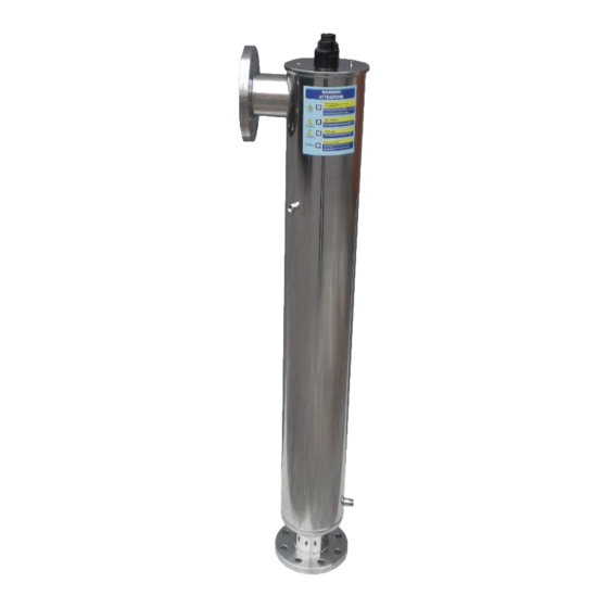
- Page 1 ULTRAVIOLET DISINFECTION IT SERIES UV 80 IT MANUAL OF INSTALLATION, USE AND SERVICING Rev. 06-2019 English 01-2015 Rev.C...
-
Page 2: Table Of Contents
INDEX 1. Introduction .................................2 2. General Principles ...............................3 3. Permissible operating range (data) according to ÖNORM M5873-1:2001 ............6 4. Instruction for installation and servicing ......................8 4.1. Installation scheme recommended ..........................9 5. The UV Chamber Installation ...........................12 5.1. Assembling of the UV chamber..........................12 6. -
Page 3: Introduction
1. Introduction This manual is for the following models of UV IT Series. UV 80 IT This Pressure UV Systems is manufactured by S.I.T.A. s.r.l. These operating instructions contain important information for the operation and maintenance of the equipment. Please ensure that these operating instructions are carefully read by all relevant persons before putting into operation, to ensure the safe use of the UV system. -
Page 4: General Principles
2. General Principles The UV 80 IT SERIES sterilizers have been planned specially for destroying harmful bacteria and viruses present in your water. Their working is based on a physical principle which is a warrant of security: the output of ultra-violet irradiation. - Page 5 Attention: Working on live equipment is forbidden. INFORMATION TO USERS pursuant to art. 14 of the 2012/19 / EU DIRECTIVE OF THE EUROPEAN PARLIAMENT AND OF THE COUNCIL of 4 July 2012 on waste electrical and electronic equipment (WEEE) The crossed bin symbol on the appliance or on its packaging indicates that the product at the end of its useful life must be collected separately and not disposed of together with other mixed urban waste.
- Page 6 INSTALLATION GUIDANCE The reactor control panel utilises air cooling. The following guidelines must be adhered to when locating the unit. The reactor and control panel must not be located in a position where the ambient air temperature exceeds 40ºC. The reactor and control panel must not be located adjacent to other equipment that directly emit heat The reactor and control panel must not be located adjacent any chemical equipment that is likely to emit fumes.
-
Page 7: Permissible Operating Range (Data) According To Önorm M5873-1:2001
3. Permissible operating range (data) according to ÖNORM M5873-1:2001 Permissible range of operation is the result of typetest according to ÖNORM M5873-1:2001. For each UV-transmittance (%) is reported the minimum reference irradiance (W/m ) and the maximum flow (m /h) considering that the minimum Reduction Equivalent Fluence demanded is 400 UV 80 IT UV-trasmittance UV-trasmittance... - Page 8 92,7 165,70 50,80 92,9 167,22 51,83 93,1 168,75 52,86 93,3 170,28 53,91 93,5 171,81 54,98 93,7 173,35 56,05 93,8 174,89 57,14 94,0 176,43 58,23 94,2 177,98 59,34 94,4 179,53 60,47 94,5 181,08 61,60 94,7 182,63 62,74 94,9 184,19 63,90 95,0 185,74 65,06 95,2...
-
Page 9: Instruction For Installation And Servicing
MAINTENANCE The UV System of UV 80 IT SERIES have been projected and realized by S.I.T.A. Srl with simple and functional principles which make the checking procedures and the periodical servicing particularly easy. -
Page 10: Installation Scheme Recommended
4.1. Installation scheme recommended... -
Page 13: The Uv Chamber Installation
5. The UV Chamber Installation 5.1. Assembling of the UV chamber ● Unscrew the s/s sleeve bolts (A) from both sides by using the key supplied. ● Insert the quartz sleeves (B) by using the special bar supplied and the o-rings 38x4 (C) on both sides of the quartz sleeves. - Page 14 ● Screw again the s/s sleeve bolts on both sides of the UV chamber, and carry out the hydraulic test, verifying that the o-rings are watertight and that no water leaks outside the sleeve bolts or inside the quartz sleeves. ●...
- Page 15 ● Each lamps has 2 wires connected from the top to the bottom .Lamps must be inserted into the chamber with these wires in the opposite side to the sensor. To do this the two pins (signed with the red circle in the photo below) must be in the opposite side to the sensor.
- Page 16 ● Screw the Ø 1 ¼” ring nuts (F) on the s/s sleeve bolts. ● Mount the o-ring (I) (4112 type) on the measuring window (L) and screw this one on the Ø 1” bush welded in the middle part of the UV chamber.
-
Page 17: Safety Measures And Regulations
Insert the sensor (M) inside the measuring window and screw the ring nuts. Finally, connect the pertinent electrical cable. 6. Safety measures and regulations... -
Page 18: Elettricity
The equipment must be installed, put into operation and maintained by trained specialists. The owner and/or user must ensure that the operating personnel have been suitable instructed. The equipment has been subjected to a hazard analysis, corresponding precautionary measures regarding the safety of persons and domestic animals have been made. Nevertheless, it is still possible that danger could arise as a result of incorrect use, bad maintenance, material changes, etc. -
Page 19: Touch Screen Panel
The commissioning personnel must be familiar with the safety measures and regulations applicable to the country/area in which the system is installed. Turn On/Off the system The preconditions for starting are: ✓ Water is flowing through the vessel. ✓ The electrical panel is feeded ✓... -
Page 20: Setting Menu
Main screen of the system. It displays the parameters of flow rate, transmittance, temperature, irradiation, lamps hour meter and quartz cleaning system (if available). It also displays the lamps power. In case of alarm flashing "ALARM button” is displayed. Temperature Trasmittance Flow rate UV irradiance... -
Page 21: Lamps Menu
Return button Electric board menu Water parameters Sensor menu Cleaning System Info software DATALOG - EVENTS -) It allows to visualize the datalog and the events of the system. LANGUAGES MENU -) It allows to change the language both of the user and the system. MAINTENANCE MODE -) It allows to set the system in maintenance mode (disable the alarms and stop the cleaning system motor). - Page 22 ➢ N° lamps: represents the number of lamps of the UV system. ➢ Lamps lifespan: represents the lamps maximum working hours. ➢ Residual lamp life: represents the lamps remaining working hours. It 'a countdown indicative of the residual lamps life from their last exchange. When this countdown reaches zero, an alarm alerts the user that lamps must changed.
- Page 23 Module 1: Manual Enabling this option the user can adjust the lamps power level manually from a minimum of 50% to a maximum value of 100%. With the RESET button user can restore the default value to 100%. Module 2: Flow Pacing Enabling this option user can set the expected water flow.
-
Page 24: Panel Menu
This screen displays the parameters of temperature, power, current and voltage of each lamp. 8.4. Panel menu Submenu where the user can read and set the framework parameters of the system. The panel menu is divided into 4 modules. - Page 25 Module 1: Model ➢ Model: displays the control panel type. ➢ Absorption: shows the theoretical panel value of absorption preset by password menu ➢ Panel temperature: displays the temperature inside the panel in Celsius Degree. Important! If the temperature is higher than the threshold then the system will automatically turn off. In this case, a message will appear “SHUTDOWN DUE TO HIGH PANEL TEMPERATURE”.
- Page 26 Module 2: Timer ➢ Date: shows the current date. ➢ Time: shows the current time ➢ On/Off Timer: it allows to able/disable the automatic start and stop of the lamps. ➢ On: sets the time for automatic start up. ➢ Off: sets the time for automatic shutdown. Press RESET to restore the factory setting value.
- Page 27 ➢ Remote OFF delay: It allows to set the shutdown delay from remote contact. This setting can helps when the remote ON/OFF contact is directly connected to a flow switch. By increasing the remote off delay the system does not shut off for short flow stop. Important! The remote off delay cannot be too long otherwise the chamber may reach over temperature.
-
Page 28: Sensor Menu
8.5. Sensor menu Submenu where the user can read and set the parameters that control the irradiance/temperature sensor. With the button you can switch from screen 1 to screen 2. Screen 1: ➢ Temperature: displays the collector temperatures in Celsius Degrees. ➢... - Page 29 Important! The sensor must be calibrated at every lamps changing. Important! To calculate the radiation factor % it is necessary that the lamps reach the steady state conditions. Delay time depends on lamps type and water temperature. We therefore advice to wait 30 min from the system start up.
- Page 30 ➢ Max temperature: settable threshold that defines the maximum acceptable temperature in the plant before shut off for safety. Important! In case of absence of flow the UV lamps can increase water temperature. This can damage lamps and UV system. If the temperature is higher than the threshold then the system will automatically turn off.
-
Page 31: Automatic Cleaning System
8.6. Automatic cleaning system Submenu where the user can read and set the parameters that control the automatic cleaning system. ➢ Auto Cleaning ON/OFF: It allows to able/disable the automatic cleaning system. ➢ Wipers cycles: counter displays the number of wiper cycles Touch the button to reset the numbers of wiper cycles . -
Page 32: Parameters
8.7. Parameters Submenu where the user can read and set the water parameter. With the button you can switch from screen 1 to screen 2. Screen 1: ➢ Flow rate: displays the flow rate in mc/h. ➢ Transmittance: shows the water transmittance read by the UVT meter sensor in %. ➢... - Page 33 Screen 2: this screen allows to set alarm thresholds. ➢ Max Flow: settable threshold that defines the maximum acceptable flow rate in the plant before having the alarm. If the “High Flow Shutdown” button is activated the plant shut off for safety. Factory setting: 9999 mc/h ➢...
-
Page 34: Datalog - Events
8.8. Datalog - Events Touching “datalog- event” button either the datalog screen or the event screen can be visualized. Events Datalog menu Datalog screen: Submenu where the user can view the trend of system parameter: Parameters: ➢ Irradiance (Dose) ➢ Temperature (chamber and panel) ➢... - Page 35 Important! The files stored on a USB pen have .dat extension. Those files can be converted to .csv file, accessible with software Excel, Calc or similar, with a special conversion software. Obtain details on how to get the software. Events screen: In this section alarms and events of the system are displayed: The events are displayed in chronological order.
-
Page 36: List Of Alarms And Troubleshooting
8.9. List of alarms and troubleshooting Each alarm activates the main relay (dry contact and 24 Vdc output). The message ALARM! on the Main Screen starts flashing. Press “ALARMS” on the screen to visualize the alarms. The screen lists all the possible alarms and shows the status of lights: Push to access to Lamp Status Screen... - Page 37 This alarm doesn’t switch the main relays. → It’s visualized in case the countdown of lamp life reaches 0 h. This means that LAMPS EXHAUST the lamp worked for more than their lifespan. Possible Causes: Solutions: ✓ Lamp lifespan finished ✓...
- Page 38 This alarm shut down the panel. It’s visualized in case the water temperature inside the chamber is higher then the settable threshold level (factory setting 50°C) Possible Causes: Solution: ✓ No Flow ✓ Check pumps, valves ✓ Non correct signal from the ✓...
- Page 39 cycling of low flow shut down. HIGH FLOW If shout down option is activated this alarm shutdowns the panel . It’s visualized in case the flow rate inside the chamber is higher than the settable threshold level (factory setting 9999 mc/h) Possible Causes: Solution: ✓...
-
Page 40: Spare Parts
9. Spare parts... -
Page 41: Warranty Condition
In no case the integral replacement of the product is forseen and any responsibility of sita is excluded for delays in the delivery of the goods to the customer, for claims of third parties towards the customer, for losses of goods, costs (installation, servicing and maintenance, transports, and so on) and damages of the customer due to the defect. -
Page 42: Declaration Of Conformity
Unit produced in the factory of: S.I.T.A. Italian Company for Water Treatment EC DECLARATION OF CONFORMITY The undersigned hereby declares, under full responsibility, that the unit: UV STERILIZER IT SERIES UV 80 IT MODEL IS IN COMPLIANCE WITH • 2014/35/UE (low voltage directive) •...
Need help?
Do you have a question about the IT Series and is the answer not in the manual?
Questions and answers