
Summary of Contents for Technifab Products Cryogenic Tank Switcher
- Page 1 Technifab Vacuum Jacketed Tank Switcher Installation Manual LT-33020(2) ©2013 Technifab Products, Inc.
-
Page 2: Table Of Contents
It may also be used to alert ©2013 Technifab Products, Inc. All rights reserved. No part of this manual may be reproduced, transcribed, stored in a retrieval system, translated into any language or... -
Page 3: Safety
Caution - Care should be taken around safety relief valves and gas vent line outlets in case cold cryogenic gas or liquid should ever be expelled. Caution - Technifab Products Inc. recommends routing the discharge lines from pressure relief devices to a safe place of discharge. The outlet of the discharge line should not be in a location where it could injure people or damage anything should cold cryogens be expelled. -
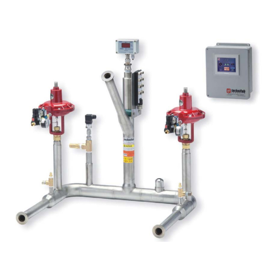
Page 4: Components Included
Note: Most tank switchers include a cryogenic inlet filter installed inside the inlet female bayonets. You should use an orange colored bayonet clamp (two shown) to indicate inlet filters inside the bayonet connection. Please check your shipping document for a complete list of components included. LT-33020(2) ©2013 Technifab Products, Inc. -
Page 5: Installation And Setup
The control box comes with a standard NEMA 5-15R male power connector at the end of the cable. Do not plug the unit in at this time. LT-33020(2) ©2013 Technifab Products, Inc. - Page 6 Note: If the outlet is being connected to a Techniguard vacuum jacketed pipe system you may want to refer to LT-30121, the Techniguard System Installation Manual for B-Series and R-Series VJP, which covers bayonet and vacuum-jacketed pipe installation in more detail. LT-33020(2) ©2013 Technifab Products, Inc.
-
Page 7: Alarm Output
24Vdc Pos. (+) The pin closest to the notch in the connector is the ground and the positive terminal is furthest away (see photo). Refer to the specifications section for electrical signal specifications. 24Vdc Neg. (-) LT-33020(2) ©2013 Technifab Products, Inc. -
Page 8: Troubleshooting
Make sure the tank switcher inlet filter (if equipped) is not plugged. Refer to LT– 38213, Inline Cryogenic Filter Instructions, for cleaning or replacement. If the problem continues contact Technifab Products, Inc for further assistance. LT-33020(2) ©2013 Technifab Products, Inc. -
Page 9: Specifications
Technifab continuously seeks to improve its products. Customer feedback is an essential element of this process. Should any issue arise regarding this product’s performance, please immediately notify: Technifab Products, Inc. - Quality Department 812.442.0520 10339 N. Industrial Park Drive 812.442.0891 Fax P.O.
Need help?
Do you have a question about the Cryogenic Tank Switcher and is the answer not in the manual?
Questions and answers