Table of Contents
Advertisement
Quick Links
CDE
Installation and setting
instructions
Horizontal and Vertical
Position Indicator Units
with Serial Inputs
ULSP32HS & ULSP32VS
ULSP52HS & ULSP52VS
Publication Number: II104/0404
Part Number: 002070-000104
Important
These instructions must remain with the product to ensure correct
installation. If extra copies are required please contact Dewhurst plc
and quote publication number and issue
UK Customers only
If you have any problems or questions, please contact our
technical support desk direct on t 01352 793222 f 01352 793255
during office hours.
Dewhurst plc
Inverness Road Hounslow TW3 3LT United Kingdom
tel +44 (0)20 8607 7300 fax +44 (0)20 8572 5986
info@dewhurst.co.uk www.dewhurst.co.uk
Advertisement
Table of Contents

Summary of Contents for dewhurst ULSP32HS
- Page 1 Part Number: 002070-000104 Important These instructions must remain with the product to ensure correct installation. If extra copies are required please contact Dewhurst plc and quote publication number and issue UK Customers only If you have any problems or questions, please contact our technical support desk direct on t 01352 793222 f 01352 793255 during office hours.
- Page 2 The encoders can accept either one per floor inputs or parallel encoded inputs directly from the lift controller using binary, grey code or equivalent. For the full specification and other details refer to the publications detailed below. DISPLAY UNITS PUBLICATION NUMBER ULSP32HS PB145 ULSP32VS PB145 ULSP52HS...
- Page 3 GENERIC WIRING OF DISPLAY UNITS WITH SERIAL INPUTS Select power cable in accordance LIFT CONTROL PANEL with load current and volt-drop specifications LIFT WELL TRAVELLING CABLES 4 SERIAL CABLES 4 SERIAL CABLES ENCODER SER1 SER1 FLOOR ‘N’ DISPLAY DISPLAY WIRE ADDITIONAL DISPLAY(S) IN PARALLEL...
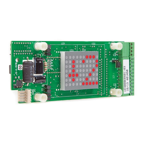
- Page 4 Generic Wiring of Display Units with Parallel Inputs REAR VIEW ULSP32HS ULSP32VS ULSP52HS ULSP52VS EEPROM SW1 Switch Settings If “Flashing Arrows” are specified, to simulate “Hall Lantern Indicators” when the lift car arrives at a landing entrance, it is necessary to set SW1 switch of the landing display to the encoded address of the floor legend for that floor.
- Page 5 ENCODER CAPABILITIES Terminal Allocation Features Terminal Features Available Allocation CH024 CH034 Available 24 max 34 max Up and Down Arrows UA, DA (PAR4) UP & DN Arrows Up and Down Gongs UG, DG (PAR5) Scrolling Arrows Up and Down Lanterns UL, DL (PAR6) Flashing Arrows Slow Down/Door Open...
- Page 6 Changing Preprogrammed Memory Integrated Circuits The EEPROM Memory Integrated Circuits are preprogrammed by Dewhurst/LiftStore with the software required to drive the displays. The EEPROM may be fitted in various locations, will be socketed, have the same number of pins and will be labelled in a similar manner to its new replacement.
- Page 7 Typical Display Faceplate Assembly DESCRIPTION ITEM Faceplate Window Insulated Spacer Display PCB Plain Washer M4 Full Nut M4 Weldstud M4 II104/0404...
- Page 8 MAINTAINING THE DISPLAY UNIT SWITCH THE POWER OFF Keep the display unit clean, dry and free of dust and other particulates. Check that the EEPROM and microprocessor ICs are fully inserted in their sockets. Check tightness of field wiring terminations and that associated plugs are secure. Replace the faceplate assembly, switch the power ON.
Need help?
Do you have a question about the ULSP32HS and is the answer not in the manual?
Questions and answers