Table of Contents
Advertisement
Quick Links
Advertisement
Table of Contents

Related Manuals for Sielco Elettronica D1-15P

Summary of Contents for Sielco Elettronica D1-15P
- Page 1 D1-15P analog module User’s guide...
- Page 2 D1-15P analog module User’s guide Sielco Elettronica S.r.l. via Edison 209 20019 Settimo Milanese (MI ) – Italia Web site: www.sielcoelettronica.com info@sielcoelettronica.com E-mail : Tel. 0248916252 0245329627...
-
Page 3: Table Of Contents
Contents 1 Installation......................... 1 1.1 Packaging check ......................1 1.2 Dimensions........................2 1.3 Fixing method ......................2 1.4 Physical module description..................3 1.5 Supply.......................... 4 1.6 Inputs ........................... 5 1.6.1 Pt100/RTD sensors inputs................5 1.7 Serial communication....................6 1.7.1 Serial link ..................... 6 1.7.2 Communication protocol................ -
Page 5: Installation
Before starting installation, it is necessary to check that the packaging contents is in compliance with your order. In the packaging there must be: # 1 D1-15P series module # 1 instruction manual Check that the model code is in compliance with the ordered code and verify that the manual edition correspond to the purchase year. -
Page 6: Dimensions
1 Installation 1.2 Dimensions The D1-15 modules dimensions are shown in figure 1.1. Figure 1.1 - D1-15P module dimensions 1.3 Fixing method All D1 series products are provided by a plastic support for fixing on normalized DIN EN rail and by a shielding serigraphed cover. -
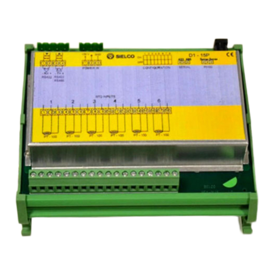
Page 7: Physical Module Description
1.4 Physical module description 1.4 Physical module description Figure 1.2 - D1-15P scheme... -
Page 8: Supply
1 Installation Description [C1] RS422/485 serial channel connector +24 Vdc supply connector [C2] Analog inputs screws [M1] [M2] Pt100/RTD sensors inputs screws DIPSW Protocol and device address selection dipswitch Led LA Supply led Led LM Selftest led (normally blinking) Led TX Transmitted data led Led RX Received data led 422 485 RS422 or RS485 line selection jumper 3 with with cable resistance compensation or 2... -
Page 9: Inputs
1.6 Inputs 1.6 Inputs 1.6.1 Pt100/RTD sensors inputs To D1-15P modules can be connected Pt100 sensors. WARNING! Be sure that the sensors used are in compliance with IEC 751 standard. Choosing the sensor, be sure that the wires connected to the sensor are electrically isolated from its metallic case. -
Page 10: Serial Communication
TX+/RX+ ←→ +24 V Table 1.1 - C1-25 - D1-15P (RS 422/485) wiring D1-15P modules are provided with configurable serial interface RS422/485, normally configurated as RS485. To change configuration you have to move the 422/485 jumper placed upper on the printed circuit... -
Page 11: Communication Protocol
NOTE At power on, the device waits 4 seconds to communicate. 1.7.3 Device identification To D1-15P can be assigned an identification address between 1 and 31 through binary notation, using selector from 4 to 8 of dipswitch (see table 1.2). -
Page 12: Serial Cable
1 Installation 1.7.4 Serial cable Use shielded cable with one (RS-485) or two (RS-422) twisted pair in compliance with EIA RS-485 or EIA RS-422; using the shield for ground. Recommended cable: Belden 9841 (RS-485); 9842 (RS-422) Maximum signal loss: 6 dB Maximum line capacitance: 100 nf Maximum line length: 1200 m Line impedance: tra 100 e 120 ohm... - Page 13 3 of [C2] connector. PT100 configuration The D1-15P has a jumper to configure the input channels PT100 as 3-wire or 2 wire. The configuration is valid for all 6 channels. In 3-wire configuration, the module autonomously performs two readings 1 °...
-
Page 14: Operation
2 Operation 2 Operation 2.1 Application D1-15P module is provided with 6 input channels for temperatures. Temperature values are acquired using two or three wires Pt100 sensors with automatic cable resistance compensation; acquired temperature values are recorded in tenth degrees on a range from -2000 to +4000; for example, a value of 275 means a temperature of 27.5°C. -
Page 15: A Gates List
A.1 Numeric Gates (Holding Registers) A Gates list A.1 Numeric Gates (Holding Registers) Address Description Byte Range Restart number 0: 255 Pt100 #1 temperature -2000:+4000 Pt100 #2 temperature -2000:+4000 Pt100 #3 temperature -2000:+4000 Pt100 #4 temperature -2000:+4000 Pt100 #5 temperature -2000:+4000 Pt100 #6 temperature -2000:+4000...
Need help?
Do you have a question about the D1-15P and is the answer not in the manual?
Questions and answers