Table of Contents

Summary of Contents for WPT POWER PILOTLESS
- Page 1 PILOTLESS™ MECHANICAL POWER TAKE-OFF Installation & Maintenance Manual 6” THRU 14” WPT Power Corporation 1600 Fisher Road - Wichita Falls, TX 76305 P.O. Box 8148 - Wichita Falls, TX 76307 Ph. 940-761-1971 www.WPTpower.com...
-
Page 2: Table Of Contents
Contents Signal Words & Definitions Introductions Product Description Exploded Views of Basic Units & Parts List for: • “C” Style Clutch assembly • “SP” Style Clutch assembly Installation Requirements for Proper Operation and Service Life Outboard Support Driving Ring Installing the Unit Clutch Adjustment Operation Disassembly... -
Page 3: Signal Words & Definitions
Signal Words & Definitions Throughout this manual there are several safety messages that must be read and adhered to in order to prevent possible loss of equipment and/or personal injury and /or loss of life. The three signal words are “Danger”, “Warning” and “Caution”. They are used to indicate the severity of the hazard and are preceded by a safety alert symbol. -
Page 4: Introductions
1.0 Introduction Warning Forward this manual to the person or persons responsible for the installation and/or operation and/or maintenance of the product described herein. Without access to this information, faulty installation, operation and/or maintenance may occur, which could result in equipment damage, personal injury and even death. -
Page 5: Product Description
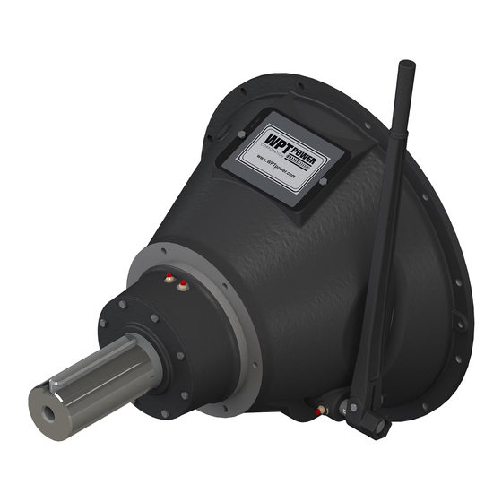
1.1 PRODUCT DESCRIPTION The WPT Pilotless™ Mechanical Power Take-Off (PTO) consists of a lever-actuated clutch with a shaft and bearings mounted in a rigid housing. The mechanical PTO is designed for inline and sideload applications on all internal combustion engines with standard SAE industrial flywheel and flywheel housing dimensions. - Page 6 EXPLODED VIEWS “C” Style Ball Bearing sliding sleeve assembly Available in sizes 6” - 10” Item Description Item Description Retaining Ring Clevis Pin Collar Clevis Pin Ball Bearing Link Retaining Ring Cotter Pin Sliding Sleeve WIM-TD-002_C Page 6 of 39...
- Page 7 CLUTCH PACK “C” Style Ball Bearing Assembly available in sizes 6”- 10” Item Description Item Description Sliding Sleeve Assembly Spring Adjustment Link Assembly Hub & Backplate Floating Plate Friction Disc WIM-TD-002_C Page 7 of 39...
- Page 8 PTO ASSEMBLY “C” Style Ball Bearing Assembly available in sizes 6”- 10” 7” PTO Shown Item Description Item Description Clutch Key Washer Shaft Clutch Pack Output Key Driving Ring Bearing HHCS External Retainer Ring Bearing Retainer Hand Lever Assembly Grease zerk Bellhouse Yoke Assembly Nameplate...
- Page 9 “C” Style Ball Bearing Assembly available in sizes 6”- 10” “C” Style The “C” style sliding assembly utilizes a sealed ball bearing design. Friction disc sizes range from 6” to 10” with our 1 plate, 2 plate or 3 plate options. WPT PTOs meet the mounting requirements of SAE J617 and SAE J620.
- Page 10 SLIDING SLEEVE ASSEMBLY “SP” Style Ball Bearing assembly available in sizes 11”- 14” Item Description Item Description Retainer Ring (Inner) Link Collar Clevis Pin Sealed Ball Bearing Cotter Pin Retainer Ring (Outer) Plug Sliding Sleeve WIM-TD-002_C Page 10 of 39...
- Page 11 CLUTCH PACK “SP” Style Ball Bearing Assembly available in sizes 11”- 14” Item Description Item Description Sliding Sleeve Assembly Washer Adjustment Ring Lever Clevis Pin Friction Disc Cotter Pin Center Plate Floating Plate Assembly Hub & Backplate WIM-TD-002_C Page 11 of 39...
- Page 12 PTO ASSEMBLY “SP” Style Ball Bearing Assembly available to fit 11”- 14” 14” PTO Shown Item Description Item Description Bearing Washer Clutch Key Clutch Pack Shaft Driving Ring Output Key HHCS Bearing Retainer Grease zerk Hand Lever Assembly Yoke Assembly Bellhouse Key Woodruff Nameplate...
- Page 13 “SP” Style Ball Bearing Assembly available to fit 11”- 14” “SP” Style The “SP” style sliding assembly utilizes a sealed ball bearing design. Friction disc sizes range from 11” to 14” with our 1 plate, 2 plate or 3 plate options. WPT PTOs meet the mounting requirements of SAE J617 and SAE J620.
-
Page 14: Installation
3.0 Installation Caution Follow safety guidelines utilizing lockout tagout procedures before and during all installation and maintenance procedures. Warning Ensure that proper rated lifting devices & procedures are followed when installing, working or maintaining unit. Failure to do so may result in equipment damage, personal injury and even death. -
Page 15: Requirements For Proper Operation And Service Life
3.1.0 REQUIREMENTS FOR PROPER OPERATION AND SERVICE LIFE 3.1.1 Preparation. Upon receipt of your WPT product, inspect for and report any evidence of damage. To avoid damage or personal injury, ensure that adequate lifting devices and hand tools are available. Compare the flywheel, flywheel housing to the bell housing, drive ring respectively to ensure that you have the correct size unit. - Page 16 3.1.5 Check flywheel face runout. Mount the indicator base on the flywheel housing and position the dial indicator tip so that its movement is perpendicular to the face of the flywheel. Position the indicator tip near the drive ring mounting bolt circle diameter. Rotate the flywheel 360 degrees applying force to the crankshaft thrust bearing.
-
Page 17: Outboard Support
3.2.0 OUTBOARD SUPPORT (if required) 3.2.1 Refer to Table 1 for the necessity of using an outboard support. OUTBOARD SUPPORT REQUIREMENT SIDELOAD APPLICATIONS IN-LINE C106 Not Required Not Required C107 Not Required Not Required C108 Not Required Not Required C110 Not Required Not Required SP111... -
Page 18: Driving Ring
3.3.0 INSTALLATION OF DRIVING RING 3.3.1 Use the drive ring provided with the PTO or remove the drive ring from the engine flywheel to use as an alignment gauge. Place the drive ring over the friction discs. Center the drive ring relative to the outer diameter of the clutch body 3.3.2 Engage the clutch by operating the hand lever. - Page 19 3.4.6 The pilotless PTO does not have critical endplay requirement, nor is there a requirement for adjustment. CAUTION: Operating handle must be mounted in the vertical position, just over center in engagement direction, to eliminate illustrations in Figure 2 excessive wear in the collar, See 3.4.7...
-
Page 20: Clutch Adjustment
If a coupling is used, ensure that it has sufficient horsepower capacity and that shafts are in line within the limits specified by the coupling manufacturer. If you are unsure about the procedure to align these shafts, consult the coupling manufacturer or WPT Power. 3.5.0 CLUTCH ADJUSTMENT The WPT mechanical PTO uses an adjusting collar to adjust for clutch wear. - Page 21 Figure 6 Operating Shaft Hand Lever Hand Lever Hex Nuts Size Torque Model Force Length Across Flats “A” lbfft (Nm) lb (kg) 13.3” (337.8) C106 66/86 (89/117) 60/78 (27/35) 13.3” (337.8) C107 66/86 (89/117) 60/78 (27/35) 13.3” (337.8) C108 71/94 (96/127) 64/85 (29/39) 13.3”...
-
Page 22: Operation
CAUTION: Do not use any automated clutch engagement device which continues to apply pressure to the hand lever after clutch is engaged. To prevent excessive wear to clutch sliding sleeve and other clutch parts, the hand lever should be allowed to rest in a vertical position with no external force applied to it once clutch is engaged. 4.0 OPERATION Where high inertia loads must be started, engaging the clutch at idle speed may stall the engine. -
Page 23: Disassembly
5.0 DISASSEMBLY WARNING: The PTO is heavy. Use approved lifting eyes and procedures to prevent accident or injury. (Refer to PTO assembly drawing or illustration in Section 2 of this manual) Use a hoist or other suitable lifting equipment to support the weight of the power take-off. Attach lifting devices at several places or use cribbing to support the PTO in a horizontal position during removal. -
Page 24: Assembly
5.3.4 Remove inner cup and shaft with bearings from PTO housing. 5.3.5 Remove shaft and bearings from PTO housing. 5.3.6 Using a suitable bearing press, remove bearings from shaft. 6.0 ASSEMBLY Refer and apply Section 3.1 throughout this section to ensure proper service life Refer to assembly drawing for each step 6.1.1 BEARING TO SHAFT ASSEMBLY... - Page 25 6.1.3 Clutch Pack Assembly 6.1.3.1 Put friction disc on backplate. (FOR SINGLE PLATE CLUTCH PROCEED TO STEP #6.1.3.6 FOR "SP" OR #6.1.3.11 FOR "C" STYLE) 6.1.3.2 Place center plate on hub, being careful to align teeth with hub teeth. 6.1.3.3 Put 2nd friction disc on center plate.
- Page 26 6.1.3.10 Assemble sliding sleeve assembly to floating plate assembly using clevis pins and cotter pins. See Figure 8 & 9 for direction of clevis pins and positioning of cotter pins. (For "SP" style clutches go to item #6.1.3.18) 6.1.3.11 For "C" style, install floating plate on hub and backplate assembly. 6.1.3.12 Assemble finger levers to adjusting ring using clevis pins and cotter pins.
-
Page 27: Maintenance
Maintenance Warning Do not allow unqualified personnel to install, adjust and/or repair the unit. Faulty workmanship could result in faulty installation, dangerous operation of the u nit, repeated costly maintenance and greatly shorten the life of the unit. Warning Do not perform maintenance work on the unit, without making sure that the machinery will remain in a safe position. -
Page 28: Maintenance Schedule
Maintenance schedule 7.1.1 The WPT mechanical PTO requires lubrication with NLGI #2 lithium-based grease. Prior to installation, grease the main shaft bearings and operating shaft. Apply grease to each fitting until grease just appears at the respective seal surfaces. Although the PTO is normally lubricated at the factory, this step will ensure that all moving parts are properly lubricated for initial use. -
Page 29: General Storage Guidelines
General Storage Guidelines Upon receipt of parts or assemblies, they should be inspected for corrosion or other related damage. If any problem is detected, contact WPT’s customer service department. It is the owner’s primary responsibility to store and protect the WPT product. Products should be stored in a manner that it is protected from the environment and outside sources, which may include but are not limited to the following:... -
Page 30: Tables
TABLES Maximum Approx. Net Maximum Input Available SAE Model/ Size Speed Weight Housing Sizes Torque lbfft (Nm) lb (kg) C106 6,5,4 171 (232) 3500 60 (27) C107 6,5,4 191 (259) 3200 72 (32) C108 5,4,3 248 (336) 3100 83 (37) C110 4,3,2 354 (481) - Page 31 Figure 11 SAE Flywheel and Housing Drawing WIM-TD-002_C Page 31 of 39...
-
Page 32: C" & "Sp" Style Lubrication Schedule
TABLES Reference J617 table 1A Distance Housing 0.019 inches (0.483mm) 0.016 inches (0.406mm) 0.012 inches (0.305mm) 0.011 inches (0.279mm) 0.010 inches (0.254mm) 0.009 inches (0.229mm) 0.008 inches (0.203mm) 0.007 inches (0.178mm) Table 5 “C” & “SP” Style Lubrication schedule Component Interval Lubrication Main Bearings... - Page 33 TABLE 7 TORQUE VALUES FOR SOCKET HEAD AND HEX HEAD CAPSCREWS SOCKET HEAD CAP SCREWS As Received Lubricated** BOLT SIZE lbfft lbfin Nm lbfft lbfin Nm INCHES 5/16 7/16 1300 1040 9/16 1860 1488 2530 2024 4400 3520 7000 5600 10400 1175 8320...
- Page 34 TABLE 7 -continued- Caution: Torque values on assembly drawings override torque values on these charts. TORQUE VALUES FOR METRIC SOCKET HEAD AND HEX HEAD CAPSCREWS 4.6 Class 8.8 Class Lubricated** Lubricated** Bolt Bolt Size Size lbf•ft lbf•in N•m lbf•ft lbf•in N•m lbf•ft lbf•in...
-
Page 35: Appendix A - General
Appendix A GENERAL DESCRIPTION REFERENCE CLUTCH ADJUSTMENT Table 2, Section 3.5 LUBRICATION Tables 6 HARDWARE TIGHTENING TORQUE SPECIFICATION DESCRIPTION THREADLOCKER OR REFERENCE NAMEPLATE BOLTS NONE BELLHOUSING TO BEARING LOCTITE 242 OR EQUAL, OR Table 7 CARRIER BOLTS NONE IF LOCKING WASHER IS BEARING RETAINER LOCK BOLT USED BEND LOCKING TAB OVER NUT... - Page 36 WPT Power’s “Product Selection Calculations” located in the Power Drivetrain Product catalog (WLB-00-001). This catalog can be found by contacting WPT Power or by visiting www.WPTpower.com. For questions regarding Sideload, contact WPT Power Applications Engineering. Warranty will not apply to any application not approved by WPT Power.
-
Page 37: Oem Clutch Pack Installation & Maintenance Instructions
OEM Clutch Pack OEM Clutch Pack Installation and Maintenance Instructions Refer to the specific WPT clutch pack drawing as needed. Installing the Clutch Pack on the Shaft: 1. See section 6.1.4 in this manual. 2. Torque specification for hub nut see Appendix A. Aligning the Friction Discs and Assembling with the Engine: 1. -
Page 38: Trouble Shooting Guide
Needed to Engagement Excessive force on operating Reduce operating force to spec Torque handle Measure bore depth, contact WPT Power Clutch Will Not Fully Seat on Flywheel bore depth too Applications Engineering Bell Housing shallow Too much or too little grease... - Page 39 WPT Power Corporation 1600 Fisher Road - Wichita Falls, TX 76305 P.O. Box 8148 - Wichita Falls, TX 76307 Ph. 940-761-1971 www.WPTpower.com WIM-TD-002_C Page 39 of 39...
Need help?
Do you have a question about the PILOTLESS and is the answer not in the manual?
Questions and answers