Advertisement
Quick Links
MegaMoto & MegaMoto Plus User Manual
Thank you for your purchase of the Robot Power MegaMoto™ or MegaMoto Plus motor
control shield for Arduino™. This manual explains the features and functions of the
MegaMoto along with some tips for successful application. Before using your MegaMoto you
must read and agree to the disclaimer printed at the end of this document. If you don't agree
please return your unused MegaMoto to Robot Power for a refund.
Note, the MegaMoto and MegaMoto plus are electrically identical Heatsinks have been
added to the Plus to increase power handling. All specifications, input-outputs and
instructions (except for current handling) apply to both units.
The Robot Power MegaMoto is a low-cost easy to connect general-purpose power amplifier
designed to work with the Arduino hardware compatible CPU units. The MegaMoto can be
configured as a single H-bridge circuit or as two independent half-bridge circuits. While
designed for permanent magnet brushed DC motors; the MegaMoto is suitable for a wide
range of DC loads as long as they are within the current and voltage envelope of the device.
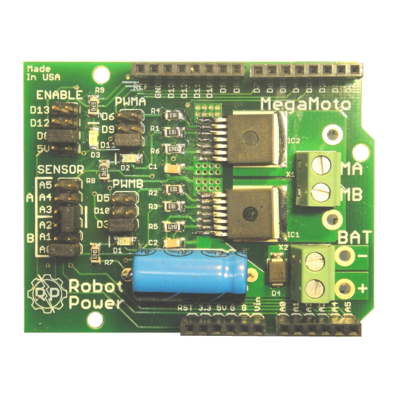
Figure 1. MegaMoto top view
Version 1.6 - May 28, 2012
1
Advertisement

Summary of Contents for Robot Power MegaMoto
- Page 1 MegaMoto & MegaMoto Plus User Manual Thank you for your purchase of the Robot Power MegaMoto™ or MegaMoto Plus motor control shield for Arduino™. This manual explains the features and functions of the MegaMoto along with some tips for successful application. Before using your MegaMoto you must read and agree to the disclaimer printed at the end of this document.
-
Page 2: Specifications
Your actual current capacity will vary based on the type of load, the length and size of wires, power supply capability and other factors. 2. Input Output connections and Jumper Settings Figure 2. MegaMoto connections and jumpers Version 1.6 - May 28, 2012... - Page 3 LED Indicators The MegaMoto has three LEDs used for visual indication of the state of the unit. The Enable LED is red and when lit shows that the power chips are enabled. The green PWMA/B LEDs show the presence of an input signal to the power chips. The brightness of the PWMA/B LEDs will vary with the duty cycle of the input signal.
- Page 4 When the MegaMoto is configured as an H-bridge the current sense output of the connected sensor outputs properly reflects the current through the bridge in either direction.
- Page 5 Thus the MegaMoto supports both variable speed and direction of a single load. Since the MegaMoto supports 100% ON and OFF periods for the inputs, you may use binary signals to activate the power chips if variable speed is not needed.
- Page 6 H-Bridge mode is the most common configuration for driving DC motors. It allows each MegaMoto to drive one DC motor in forward and reverse with variable speed. Each Arduino base unit can support up to three stacked MegaMotos and hence three independently controlled motors.
- Page 7 PWM selection headers as shown in Figure 6 above. It is possible to used three stacked MegaMoto units in ganged half- bridge mode to drive a large brushless as each ganged MegaMoto acts like a single half- bridge circuit.
- Page 8 If several MegaMoto units are stacked onto an Arduino base it is possible to use a single digital pin to enable/disable all of the MegaMotos. This does not allow individual enable/disable functions but can be used if all the loads (motors) are always enabled or disabled together.
- Page 9 If you have five motors that always operate together or in identical groups there is no reason why five or more MegaMoto units cannot be stacked up. This might prove unwieldy from a physical standpoint but electrically it will work.
- Page 10 However, if the two or more MegaMoto units are stacked on an Arduino it is acceptable to chain from one unit to the next as long as a good connection is made to each unit and the wire is of sufficient size to cause negligible voltage drop at the load current.
- Page 11 Often their voltage will increase until the extra power is dissipated. If the MegaMoto is operated at 24V with a power supply of this type it is possible to exceed the maximum rating of the device and destroy the power chips.
- Page 12 You can contact us at the following address: Robot Power 31808 8 Ave. S. Roy, WA 98580 USA 253-843-2504 support@robotpower.com Thanks again for purchasing the MegaMoto and best of luck with your projects. The Robot Power Team Version 1.6 - May 28, 2012...
- Page 13 Robot Power’s liability is limited to replacement of defective DOA units. By installing and using this unit you are agreeing to these terms. If you do not agree you may return any unused units to Robot Power for a refund. Version 1.6 - May 28, 2012...
Need help?
Do you have a question about the MegaMoto and is the answer not in the manual?
Questions and answers