Table of Contents
Advertisement
Quick Links
Advertisement
Table of Contents

Subscribe to Our Youtube Channel
Summary of Contents for FLEX-CORE L40
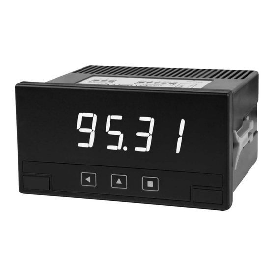
- Page 1 UNIVERSAL ANALOG INPUT DIGITAL PANEL METER OWNERS MANUAL WWW .FLEX-CORE.COM PHONE (614) 889-6152 sales@fle x-core.com TECH. ASSISTANCE (614) 876-8308 Div. Morlan & Associates, Inc. 4970 Scioto Darby Rd. Hilliard, Ohio 43026 FAX # (614) 876-8538...
-
Page 2: Ordering Guide
1. ORDERING GUIDE Configure a model number in the format below, where ordered items are separated by commas: Example: L40, JS, CP, RL1, RL2, CASE1 Set jumpers for 4-20 mA input. Scale display so that 4 mA =0, 20 mA = 500.0 . -
Page 3: Table Of Contents
2. TABLE OF CONTENTS Ordering Guide ....................2 Table of Contents ..................... 3 Product Introduction ..................4 Receiving & Unpacking ..................5 Safety Considerations ..................5 Connector Wiring Overview ................6 Factory Default Settings ................... 7 Output & Control Module Overview ..............8 Opening the Case and Setting Jumpers............ -
Page 4: Product Introduction
The base L40, as shipped by Flex-Core, is set up so that a 0-400 Vac input reads 0-400. To change that default range, pry off the meter faceplate, push out the electronics, and move one or two jumpers depending on the range, as explained in this manual. -
Page 5: Receiving & Unpacking
4. RECEIVING & UNPACKING Your meter was carefully tested and inspected prior to shipment. Should the meter be damaged in shipment, notify the freight carrier immediately. In the event the meter is not operable, contact your seller and return the meter for repair or replacement. Please include a detailed description of the problem. -
Page 6: Connector Wiring Overview
6. CONNECTOR WIRING OVERVIEW Instrument Rear view Signal Connections Relay Connections (optional) RS485 Connections (optional) UL 61010-1 requires a 250 mA slow-blow fuse for power > 50 Vac/dc, or a 400 mA slow-blow fuse for power < 50 Vac/dc. Analog Output Connections (optional) Power Connections - 6 -... -
Page 7: Factory Default Settings
7. Factory Default Settings Unless the JS customer jumper setting option or the CS jumper setting and programming option has been ordered, out-of-the-box L40 units are set up with the following factory default settings: Range ..........400 Vac Scaling and decimal point: ....0 to 400 Vac = 0 to 400 Alarms 1 &... -
Page 8: Output & Control Module Overview
An Option 2 Board can plug into the Option 1 Board if installed. This is another single 8A relay board. For example, use of this second board allows an L40 to have and analog output and a relay output, or to have two relay outputs. -
Page 9: Opening The Case And Setting Jumpers
9. Opening the Case and Setting Jumpers The case has to be opened and jumpers need to be placed to select signal types and ranges other than the factory default setting of 400 Vac. To open the case, unplug all screw-clamp con- nectors. - Page 10 AC voltage & current Jumpers S Jumper T 400 Vac 200.0 Vac 20.00 Vac 2.000 Vac 200.0 mAac 60.00 mAac 5.00 Aac 20.00 mAac DC voltage & current Jumpers S Jumper T ±400 Vdc ±200.0 Vdc ±20.00 Vdc ±2.000 Vdc ±200.0 mAdc ±60.00 mAdc ±5.00 Adc...
-
Page 11: True Rms Ac Voltage Or Current Input
10. True RMS AC Voltage or Current Input True RMS voltage and current ranges: The L40 computes true RMS. The meter’s factory default signal range is 400 Vac. A total of 6 voltage ranges and 2 current ranges are jumper selectable. The 400 Vac range is suitable for 480 Vac 3-phase measurements, but can only be CE safety rated to 400 Vac due to a 3 mm creepage distance. -
Page 12: Dc Voltage Or Current Input (Including 4-20 Ma Process)
11. DC Voltage or Current Input DC voltage and current ranges: A total of 6 voltage ranges and 2 current ranges are jumper selectable. Applications include the measurement of 12 or 24 Vdc battery voltages, and other DC sources up to 400 V. The 60 and 200 mV ranges are can be scaled for use with current shunts, which have a typical FS output of 50, 60 or 100 mV. -
Page 13: Process Signal Input
12. Process Signal Input Process Signals: Process signals as defined for the L40 are the 4-20 mA or 0-10V DC signals that are produced by transducers and transmitters for physical parameters such as pressure, level, temperature, etc. Such signals require scaling for display in engineering units. -
Page 14: Thermocouple Input
13. Thermocouple Input Ten thermocouple types: The L40 can be jumpered and programmed to read type K, J, E, N, L, R, S, B, T and C thermocouples for display of temperature in degrees C or F. Cold junction compensation: Internal cold junction compensation is selected by default, but can be disabled from the configuration menu to allow external cold junction compensation. -
Page 15: Rtd Input (Pt And Ni Probes)
14. RTD Input (Pt and Ni Probes) Pt and Ni Probes: The L40 can be jumpered and programmed to read Pt100, Pt500 or Pt1000 platinum RTD temperature probes, also Ni100, Ni200 or Ni1000 nickel RTD temperature probes, for display of temperature in degrees C or F. - Page 16 ) and a parameter named Beta allows the meter to display temperature for any measured resistance from 100 P to 100 kP . NTC probe types: To see if the L40 is compatible with specific NTC thermistor type, check the thermistor data sheet and note the parameters R and Beta.
-
Page 17: Resistance Input
16. Resistance Input Resistance ranges: The L40 can be jumpered and program- med to read resistance in two ranges: from 0 to 10 kP and 0 to 100 kP. Provision for lead wire resistance: A simple 2-connection is used from meter to the resistance under test. To compensate for errors caused by lead wire resistance, the instrument allows a fixed number of counts to be added or subtracted from the reading. -
Page 18: Rl1 And Rl2 Relay Output Options
18. A1 and A2 Relay Output Options The optional A1 relay output module fits in Option Slot 1 and plugs into the display board. The A2 relay output module fits into Option Slot 2 and plugs into a Slot 1 option board, which must be present. -
Page 19: Aot Analog Output Option
19. M1 Analog Output Option The optional M1 module provides an isolated 4-20 mA analog output. It is installed in Option Slot 1 and plugs into the display board. The 4-20 mA signal is scalable with either a positive or negative slope, and is proportional to the reading of the instrument. - Page 20 6) Select “4 mA”, and the display will show a number. Change that number to the one shown on the calibration sheet by using the Up key to increase or the Left key to decrease. Enter that value by pressing the Square key.
-
Page 21: Rs485 Serial Data Output Option
“Tool \ out.1”. Then configure the bus parameters from configuration menu “out.1 \ 485”. The S1 module can be ordered installed in the L40 instrument or separately for later installa- tion, as it does not require soldering or special configuration. -
Page 22: Front Panel Menu Overview
21. Front Panel Menu Overview 1. CONFIGURATION MENU The Configuration menu is used to set up the meter in software for specific applications. Note that both the jumpers and the software have to be set, since the meter’s software does not sense jumper settings. Jumpers have to be set before programming. While the Configuration menu is active, relay states remain unchanged from their prior state, and the output of control modules is in an “error”... - Page 23 Configuration Menu navigation example 1. The Square key enters the Configuration menu. 2. The Square key enters into the “InP” option menu. 3. The Up key moves through the menu options. 4. The Square key selects the desired range and returns to the “InP” menu. 5.
-
Page 24: Configuration Menu Details
22. Configuration Menu Details AC input (Ac). Select the full scale range. Choices are 400 Vac (factory default), 200 Vac, 20 Vac, 2 Vac, 200 mVac, 60 mVac, 5 Aac, and 20 mAac. AC measurement provides True RMS readings. DC input (dc). Select the full scale range. - Page 25 RTD input (rtd). Select the RTD type. Use the programmable offset feature (oFFS) to subtract counts for lead resistance. NTC input (ntc). NTC are thermistors with a negative temperature coefficient. Enter the resistance at 25°C and beta between 2000 and 5500, as shown on the NTC data sheet.
- Page 26 The Fast Access (K.up) menu allows specific functions to be accessed by pressing the Up key. Select “on” to select a function for fast access, “off” to deselect. Super-fast access is provided when only a single function has been selected. Pressing the Up key will then jump to that function.
- Page 27 The Tools (tooL) menu is used to confi- gure the meter. Option 1 (out.1) informs the meter of the option board installed in Slot 1. Selections are no board (oFF), relay (rELE), analog output (420), and RS485 (r.485). Steps (StEP) allows selection of the step size in counts by which readings will change.
- Page 28 Degrees (dEG) allows selection of °C or °F for temperature. Alpha (ALPh) allows selection of 0.00385 (DIN alpha) or 0.00390 (ANSI alpha) for platinum RTD probes. Cold Junction Compensation (cJc) allows internal thermocouple compensa- tion to be turned on or off. AC deadband (dbnd) allows entry of a number from 0 to 100 to display 0 for low AC signal inputs.
-
Page 29: General Specifications
23. General Specifications Meter Display Numeric display ......Four 7-segment, 14.2 mm (.56") high red LED digits Indicators ....................Two LED lamps Range ......................-1999 to 9999 Decimal point................Programmable X.X.X.X Read rate ....................3 readings/sec Step response, 0% to 99% of signal ..............300 msec Signal Types &... - Page 30 Power Requirement Input voltage ................... 18 to 265 Vac or Vdc Power consumption, normal operation ..< 1.5W without options, < 2.5W with options Power consumption, Eco mode ....< 0.3W without options, < 1.5W with options Mechanical Bezel dimensions ................96 x 48 mm (1/8 DIN) Panel cutout .................
Need help?
Do you have a question about the L40 and is the answer not in the manual?
Questions and answers