Advertisement
Available languages
Available languages
Quick Links
BOMBAS CENTRÍFUGAS PARA GRANDES CAUDALES
C E N T R I F U G A L P U M P S F O R L A R G E F L O W S
POMPES CENTRIFUGES POUR GRANDS DÉBITS
SERIE ATLAS
MANUAL DE INSTALACIÓN Y MANTENIMIENTO
INSTALLATION AND MAINTENANCE MANUAL
MANUEL D'INSTALLATION ET D'ENTRETIEN
Advertisement

Related Manuals for ILM ATLAS AT0400

Summary of Contents for ILM ATLAS AT0400
- Page 1 BOMBAS CENTRÍFUGAS PARA GRANDES CAUDALES C E N T R I F U G A L P U M P S F O R L A R G E F L O W S POMPES CENTRIFUGES POUR GRANDS DÉBITS SERIE ATLAS MANUAL DE INSTALACIÓN Y MANTENIMIENTO INSTALLATION AND MAINTENANCE MANUAL MANUEL D’INSTALLATION ET D’ENTRETIEN...
- Page 2 ESPAÑOL IMPORTANTE: El manual que usted tiene en sus manos, contiene información fundamental acerca de las medidas de seguridad a adoptar durante la instalación y la puesta en servicio de la bomba. Por ello, es imprescindible que tanto el ins- talador como el usuario lean las instrucciones antes de pasar al montaje y la puesta en marcha.
- Page 3 previamente de forma detenida las instrucciones de instalación y servicio. • La seguridad en el funcionamiento de la máquina sólo se garantiza bajo el cumplimiento y respeto de lo expuesto en las instrucciones de instalación y servicio. • Los valores límite que figuran en el cuadro técnico no deben sobrepasarse de ningún modo.
- Page 4 contra contactos eléctricos y mecánicos estén correctamente posicionadas y fijadas. Se recomienda no utilizar las instalaciones de baño en el momento de la pri- mera comprobación de la instalación del equipo de bombeo. ADVERTENCIAS EN LOS TRABAJOS DE MONTAJE Y MANTENIMIENTO. •...
- Page 5 casos posibles e imaginables de servicio y mantenimiento. Si son necesarias ins- trucciones suplementarias o si surgen problemas particulares, no dudar en contac- tar con el distribuidor, o directamente con el constructor de la máquina. 3. INSTALACIÓN Y MONTAJE GENERAL •...
- Page 6 • Para el correcto funcionamiento de la bomba se debe de proceder al ceba- do del prefiltro de la bomba hasta que el agua aflore por el conducto de aspi- ración.( Fig.3) Fig. 3 EMPLAZAMIENTO • Se aconseja el montaje de la bomba por debajo del nivel del agua de la pis- cina o estanque.
- Page 7 INSTALACIÓN ELÉCTRICA • La instalación eléctrica deberá de disponer de un interruptor general de corte omnipolar. • El cable utilizado para la conexión de la bomba debe llevar terminales para su conexión a los bornes del motor de la bomba. •...
- Page 8 • Utilizar un cable de conexión tipo H07 de sección adecuada para la intensi- dad consumida por el motor de la bomba. • Antes de conectar el motor, comprobar el tipo de protección necesaria. • Ajustar convenientemente el valor del térmico según las necesidades de cada bomba.
- Page 9 • Las bombas en ningún caso pueden trabajar sin haber sido llenadas previa- mente de agua, ya que de lo contrario, ello puede dañar la junta mecánica provocando pérdida de agua por ésta. (Fig.3) • Comprobar que el sentido de rotación del motor sea el correcto, mediante el ventilador situado en la parte trasera del motor.
- Page 10 del fabricante, o en su defecto dirigirse al Servicio de Asistencia Técnica más próximo. • Si el amperaje es más elevado, consultar con el fabricante. • Vaciar la bomba en los casos que tenga que permanecer algún tiempo sin funcionar, principalmente en países fríos donde pueda existir peligro de con- gelación.
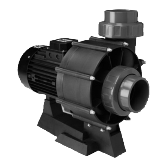
- Page 11 7. PRESTACIONES 7.1. DESCRIPCIÓN DEL PRODUCTO Y SUS ACCESORIOS. El cuerpo de la bomba está construido con termoplásticos de última generación. La turbina está construida en bronce y tanto el cesto del prefiltro como el eje del motor en acero inoxidable. Los motores que se suministran con el conjunto motor bomba han sido protegidos con IP-55 y acondicionados para soportar ambientes calurosos y niveles de hume- dad elevados.
- Page 12 CODIGO POTENCIA DIMENSIONES Ø C AT0400-SP AT0550-SP AT0750-SP AT1000-SP AT1250-SP 12.5...
- Page 15 Nº NOMBRE DE PIEZA UNID. CÓDIGO POMO PREFILTRO HD001020 TAPA PREFILTRO HD006025 JUNTA TAPA PREFILTRO ø210 x 6.5 HD021150 CESTO PREFILTRO HD091010 PASADOR BASCULANTE HD026100 TAPÓN PURGA 1/4” HD036000 JUNTA TÓRICA TAPÓN PURGA HD021100 CUERPO PREFILTRO HD041095 JUNTA UNIÓN CUERPO PREFILTRO ø114 x 6 HD021145 JUNTA TAPA CUERPO ø288 x 4 HD021140...
- Page 16 ENGLISH IMPORTANT: The manual you are reading contains fundamental information regarding the safety measures to be adopted when installing and starting up. It is therefore of utmost importance that both the installer and the user read the instructions before assembling and starting up. 1.
- Page 17 • The operating safety of the machine is only guaranteed with the compliance and respect for that mentioned in the installation and service instructions. • The value limits stated in the table of technical specifications must under no circumstances be exceeded. •...
- Page 18 ASSEMBLY AND MAINTENANCE WORK WARNINGS. • National installation regulations should be taken into account when assem- bling and installing the pumps. • Special attention should be paid to ensure that under no circumstances water gets into the motor and the electric voltage parts. •...
- Page 19 INSTALLATION AND ASSEMBLY GENERAL • Assembly and installation of our pumps is only permitted in swimming pools or tanks complying with regulation HD 384.7.702. In case of doubt please consult a technician. • All pumps come with a two-drill foot to allow it to be fixed to the floor by means of an anchor.
- Page 20 Fig. 3 POSITIONING • It is recommended to install the pump below the water level of the swimming pool . • The pump should be installed near the pool, not further than 3 meters from the connections and between 0,5 and 3 mts below the water level. •...
- Page 21 ELECTRICAL UNIT • The electrical installation should have a general omni-pole cut-off switch • The cable used for the connection of thepump, should have terminals to be connected to the pump motor. • It is necessary to install a magneto-thermic protector. •...
- Page 22 • Use a connecting cable type H07 of a suitable section for the consumed intensity by the pump motor. • Before connecting the motor, check the necessary protection type. • Adjust the correct thermical value according to the needs of each pump. •...
- Page 23 • The pumps should never work without having been filled with water before- hand as, otherwise, this could cause a damage to the mechanical seal and eventually producing a water leak. (Fig.3) • Check that the rotation sense of the motor is correct, by checking the fan at the back of the motor (fig.5) ·...
- Page 24 • Empty the pump in cases where it must remain without use for some time, mainly in cold countries where there may be danger of freezing. • To empty the pump, remove the draining plug from the pump body. (see explosion drawing) •...
- Page 25 7. SPECIFICATIONS 7.1. PRODUCT AND ACCESSORY DESCRIPTION. The pump body is built in state-of-the-art thermoplastics. The impeller is made of bronze and both the prefilter basket and the motor shaft are made in stainless steel. The motors supplied with the pump unit have been protected by IP-55 and are pre- pared to withstand hot atmospheres and high humidity levels.
-
Page 26: At0550-Sp 4 5,5 255 255 110 115 330 200 470 530
CODE POWER DIMENSIONS Ø C AT0400-SP AT0550-SP AT0750-SP AT1000-SP AT1250-SP 12.5... - Page 27 FLOW SERIE ATLAS WITH PREFILTER FLOW SERIE ATLAS WITHOUT PREFILTER...
- Page 29 Nº NAME OF THE SPARE PART UNIT CODE PREFILTER KNOB HD001020 PREFILTER COVER HD006025 PREFILTER COVER JOINT ø210 x 6.5 HD021150 PREFILTER BASKET HD091010 HD026100 DRAIN PLUG 1/4” HD036000 DRAIN PLUG O’RING HD021100 PREFILTER BODY HD041095 PREFILTER BODY UNION GASKET ø114 x 6 HD021145 BODY COVER JOINT ø288 x 4 HD021140...
- Page 30 FRANÇAIS IMPORTANT: Le présent manuel contient des informations essentielles relatives aux mesures de sécurité à prendre dans le cadre de l’installation et de la mise en service des machines. Il est donc indispensable que tant l’installateur que l’usager lisent les instructions avant de passer au montage et à la mise en mar- che.
- Page 31 ont préalablement et attentivement lu les instructions d’installation et de mise en service. • La sécurité dans le cadre du fonctionnement de la machine n’est garantie que dans l’exécution et le respect des dispositions contenues dans les instruc- tions d’installation et de mise en service. •...
- Page 32 AVERTISSEMENTS RELATIFS À LA PREMIÈRE MISE EN MARCHE. • Avant la première mise en marche de la pompe, vérifier le calibrage des dis- positifs de protection électrique du moteur et s’assurer que les protections contre les contacts électriques et mécaniques soient correctement placés et fixés.
- Page 33 - Les vibrations de la machine. En cas d’anomalie, stopper immédiate- ment la machine et procéder aux travaux de réparation échéants. Les instructions relatives à l’installation, à l’usage et à l’entretien de la machine contenues dans le présent manuel ne prétendent pas faire l’examen de tous les cas possibles et imaginables de service et d’entretien, compte tenu de la complexité...
- Page 34 entièrement perpendiculaire et parfaitement centrée par rapport à la bouche à connecter, de façon à éviter que la pompe et le tuyau ne soient soumis à des efforts externes qui, indépendamment de gêner les opérations de mon- tage, pourraient arriver à en causer la rupture. (Fig. 2) Fig.
-
Page 35: At0750-Sp
INSTALLATION ÉLECTRIQUE • L’installation électrique devra être dotée d’un interrupteur général de coupe omnipolaire. • Le câble utilisé pour le branchement de la pompe devra être doté de pôles pour sa connexion aux bornes du moteur de la pompe. • Il faut utiliser un garde-moteur avec protection magnéto-thermique. •... - Page 36 • Utiliser un tuyau de connexion de type H07 de section valable pour l’inten- sité consommé par le moteur de la pompe. • Avant de brancher le moteur, vérifiez le type de protection nécessaire. • Il faut régler la valeur thermique selon les besoins de chaque pompe. •...
- Page 37 • Les pompes ne doivent jamais travailler sans avoir été davantage remplis d’eau car, autrement, cela pourrait éventuellement causer des problèmes au joint mécanique et en conséquence avoir des pertes d’eau. (Fig.3) • Vérifier que le sens de rotation du moteur soit correct, moyennant le venti- lateur qui se trouve a la part arrière du moteur.(fig.5) •...
- Page 38 ·• Si l’ampérage est plus élevé, contactez le fabricant. • Vider votre pompe si elle doit rester quelque temps sans fonctionner, surtout dans les régions froides à risque de gel. • Pour vider la pompe, enlever le bouchon de purge du corps de la pompe (voir dessin pièces détachées).
- Page 39 7 - PRESTATIONS 7.1. DESCRIPTION DU PRODUIT ET DE SES ACCESSOIRES Le corps pompe a été construit avec thermoplastiques de dernière génération. La turbine est construite en bronze et tant le panier du préfiltre comme l’axe moteur sont en acier inoxydable. Les moteurs livrés dans le cadre du bloc moteur-pompe ont été...
- Page 40 CODE POTENCE DIMENSIONS Ø C AT0400-SP AT0550-SP AT0750-SP AT1000-SP AT1250-SP 12.5...
- Page 41 DÉBIT SERIE ATLAS AVEC PREFILTRE DÉBIT SERIE ATLAS SANS PREFILTRE...
- Page 43 Nº NOM DE LA PIECE UNIT. CODE MANETE PREFILTRE HD001020 COUVERCLE PREFILTRE HD006025 JOINT COUVERCLE PREFILTRE ø210 x 6.5 HD021150 PANIER PREFILTRE HD091010 GOUJON BASCULANT HD026100 BOUCHON DE VIDANGE 1/4” HD036000 JOINT TORIQUE BOUCHON VIDANGE HD021100 CORPS PREFILTRE HD041095 JOINT UNION CORPS PREFILTRE ø114 x 6 HD021145 JOINT COUVERCLE CORPS ø288 x 4 HD021140...
Need help?
Do you have a question about the ATLAS AT0400 and is the answer not in the manual?
Questions and answers