Table of Contents
Advertisement
Quick Links
1
2
ON-BOARD WEIGHING SYSTEMS
PNT9700 User's Manual
Installation Calibration Operation
(Version 4.00)
Pacific Northwest Technologies
Unplug the connector from the back of the meter before jump-starting,
Do not use pencils or other sharp-pointed objects to press the meter's keys.
battery-charging, or welding on the truck
Advertisement
Table of Contents

Summary of Contents for Pacific Northwest Technologies Accuweigh PNT9700
- Page 1 PNT9700 User’s Manual Installation Calibration Operation (Version 4.00) Pacific Northwest Technologies Unplug the connector from the back of the meter before jump-starting, Do not use pencils or other sharp-pointed objects to press the meter’s keys. battery-charging, or welding on the truck...
-
Page 2: Table Of Contents
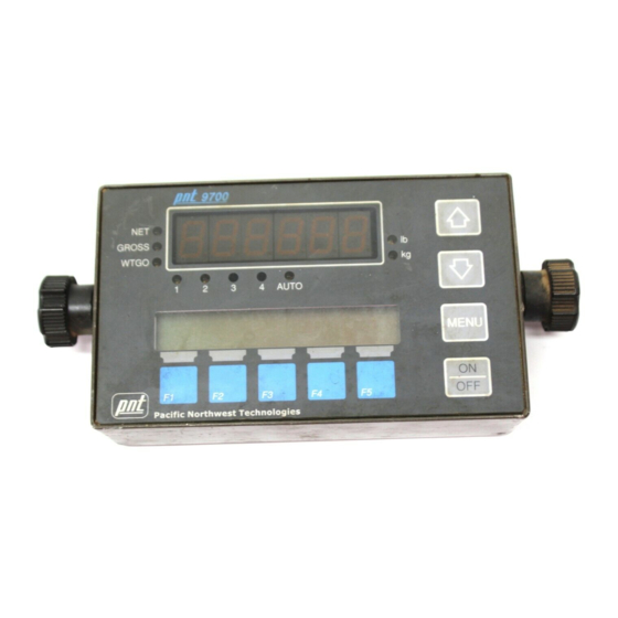
Chapter 8 Maintenance ..........45 Daily Inspections ..............45 Weekly Inspections ............... 45 ON-BOARD WEIGHING SYSTEMS Chapter 9 Special Operations ......... 47 Entering the Weight-to-go Limits ..........47 Setting For Weight-to-go ............51 Setting the Transmitter Model ..........52 Contents Chapter 10 Using Multiple Trailers ........ - Page 3 The PNT 9700 meter receives the digital signal from the transmitter and interprets and displays it as a weight in pounds or kilograms. Two displays are used on the front of the meter. The top LED display shows the weight of the load and can easily be switched between ON-BOARD WEIGHING SYSTEMS truck, trailer, or total weight.
-
Page 4: Chapter 1 Introduction
INTRODUCTION CHAPTER 1 INTRODUCTION The labels for the five blue soft keys along the bottom of the meter will be shown similarly in the bottom line of the information display, immediately above the key, like the The PNT 9700 meter has two menus used for setup and calibration, example to the right of this paragraph. -
Page 5: Chapter 2 Meter Setup
METER SETUP CHAPTER 2 METER SETUP SETTING THE LOAD UNITS (LB OR KG) It is important to see if the meter is displaying weights in kilograms INTRODUCTION (kg) or pounds (lb). Look at which of the small red LED lamps is on at the right of the weight display, next to the lb or kg label. -
Page 6: Setting The Grad Size
METER SETUP METER SETUP SETTING THE GRAD SIZE SETTING FOR NET OR GROSS The grad size, or graduation, allows the meter to display the load The NET weight refers to the weight of the load; it does not include weight in either 10, 20, 50, or 100 lb or kg increments. the weight of the truck and/or trailer. -
Page 7: Chapter 3 Calibration
CALIBRATION CHAPTER 3 CALIBRATION ENTERING THE EMPTY WEIGHT INTO THE METER Before entering the empty weights into the meter, make sure the INTRODUCTION Setting For Net Or meter display is set to GROSS (refer to Chapter 1, Gross Weight) . Also, make sure the truck and trailer are empty and The calibration process allows you to fine tune your weighing system to the trailer is on the ground with the meter cable connected. - Page 8 CALIBRATION CALIBRATION 5. The last number of the weight display will be flashing, telling you It will then show that number is ready to be changed. To change the number’s value, press the key. 9. The last number of the weight display will be flashing, telling you To select a different number, press the key.
-
Page 9: Entering The Loaded Weight
CALIBRATION CALIBRATION ENTERING THE LOADED WEIGHT INTO THE METER 5. The last number of the weight display will be flashing, telling you that number is ready to be changed. The following steps can be completed only after having your loaded truck weighed at a certified and accurate platform scale. -
Page 10: Advanced Calibration
CALIBRATION CALIBRATION ADVANCED CALIBRATION It will then show Another way to enter the loaded weight into the meter is with the advanced calibration feature. This method allows the calibration of several trucks to be centrally controlled. The driver does not have to enter the setup mode of the meter, even for calibration. - Page 11 CALIBRATION 4. Enter the number that was earlier recorded as the number shown on the meter’s weight display for channel 1 while sitting on the platform scale. Change the numbers in the same manner as then setting the original loaded-weight calibration (shown in the previous section of this chapter).
-
Page 12: Chapter 4 Operating The Meter
OPERATING THE METER CHAPTER 4 OPERATING THE METER 2. The weight-display window will momentarily show INTRODUCTION then switch to the appropriate weight. The red LED lamp labeled AUTO will turn on and the LED lamps labeled 1 and 2 will Now that the meter is set up and calibrated, it will continuously alternately turn on, depending on which channel is being monitor the truck’s load. -
Page 13: Recalling The Tare Weight
OPERATING THE METER OPERATING THE METER 3. An error message may be shown 4. Press the appropriate key to select the desired time. for 5 seconds in the information display if the tare weight of channel 1, for example, has drifted more than 5. - Page 14 OPERATING THE METER OPERATING THE METER and the weight display will show and the weight display will show 3. To find the cal factor for the truck (channel 1) channel, press the 8. To find the cal factor for the trailer (channel 2) channel, key until the press the information display shows...
- Page 15 OPERATING THE METER After recording or resetting the cal factor numbers, press key. The information display will briefly show and then return to normal operation. Unplug the connector from the back of the meter before jump-starting, Do not use pencils or other sharp-pointed objects to press the meter’s keys. battery-charging, or welding on the truck...
-
Page 16: Chapter 5 Troubleshooting
TROUBLESHOOTING CHAPTER 5 TROUBLESHOOTING The red-banded wire may be damaged between the load cell and the channel 1 transmitter. Troubleshooting is a systematic process of testing, identifying, and eliminating areas of the weighing system that are causing problems or a. The load cell connected to the red-banded wire of channel 1 may malfunctions. - Page 17 TROUBLESHOOTING TROUBLESHOOTING The channel 1 wires are shorted Channel 1 is not connected to its together or shorted to the truck transmitter. frame. a. The channel 1 wire may have been disconnected at the back of a. Disconnect the channel 1 wires from the back of the meter. If the the meter.
- Page 18 TROUBLESHOOTING TROUBLESHOOTING The signal from the channel 2 b. If the voltage is good, then make sure the power lead is transmitter is not being received at connected directly to the battery. Power from any other source may be too “noisy”. the meter.
-
Page 19: Chapter 6 Test Mode
TEST MODE RECORDING TEST NUMBERS CHAPTER 6 TEST MODE INTRODUCTION 1. Press the key to get the Test numbers provide a way to verify that your system’s load cells are If you do not continue with the operation within 15 seconds, the working as they should. - Page 20 TEST MODE 6. Press the key to display the channel 2 test numbers. The numbers shown here are examples only. Your test numbers will be different. Record your test numbers in the space provided on the first page of this chapter. 7.
-
Page 21: Chapter 7 Installation
INSTALLATION CHAPTER 7 INSTALLATION MOUNTING THE TRANSMITTERS 1. Find a protected location for each transmitter. Drill two 5/16” or 8 INTRODUCTION mm mounting holes for each transmitter. The PNT 9700 meter system includes the meter, two transmitters with 2. Install the transmitters so the cable connector is easily accessible cables to connect to the load cells, one single-piece cable for the truck and is pointed in the direction the cable will go to the meter. -
Page 22: Routing The Power Cable
INSTALLATION INSTALLATION 8. Secure the cables in the cab, next to the meter, and cut them to the 4. Review all of your installations and cable routings, looking for proper length for connection to the meter. Be sure and maintain unnecessary loops, tight bends or kinks in the cables, properly the channel identification. -
Page 23: Chapter 8 Maintenance
CHAPTER 8 MAINTENANCE INTRODUCTION Proper maintenance of your PNT 9700 on-board weighing system, including preventive maintenance, is necessary to insure accurate and consistent weight readings. The best practice is to develop both daily and a weekly inspection procedures. DAILY INSPECTIONS 1. -
Page 24: Chapter 9 Special Operations
SPECIAL OPERATIONS CHAPTER 9 SPECIAL OPERATIONS 1. Press the key for 5 seconds INTRODUCTION until the information display shows This chapter describes special features of the PNT9700 indicator. 2. After releasing the key, the The WEIGHT-TO-GO feature will instantaneously show how much weight must be loaded to reach maximum legal payload. - Page 25 SPECIAL OPERATIONS SPECIAL OPERATIONS 10. When the number on the weight display matches your trailer 6. When the number on the weight display matches your truck (channel 2) weight-to-go limit, press the key to store the (channel 1) weight-to-go limit, press the key to store the weight in the meter’s memory.
-
Page 26: Setting For Weight-To-Go
SPECIAL OPERATIONS SPECIAL OPERATIONS SETTING FOR WEIGHT-TO-GO SETTING THE TRANSMITTER MODEL Look at which of the small red LED lamps is on at the left of the weight The PNT9700 will work with the Structural Instrumentation SI-9100 display, next to the NET or GROSS label. The following table shows in and M-100 12-volt transmitters. - Page 27 SPECIAL OPERATIONS 4. When finished press the key to exit the ADVANCED SETUP MENU. The information display will show To change channel 2 from the PNT9700 transmitter to the SI-9100 transmitter, do the following: 1. Press and hold the key about 15 seconds until the information display shows After releasing the...
-
Page 28: Chapter 10 Using Multiple Trailers
USING MULTIPLE TRAILERS If you want to enable the channel 2 ID feature for using multiple CHAPTER 10 USING MULTIPLE TRAILERS INTRODUCTION trailers , press the key. The PNT9700 indicator allows operators to use one truck with multiple The information display will show trailers. - Page 29 USING MULTIPLE TRAILERS If you pressed the key, the information will show 4. Only the last three numbers of the weight display will be turned on. The last number will be flashing, telling you that number is ready to be changed. To change the value of the number, press key.
- Page 30 Unplug the connector from the back of the meter before jump-starting, Do not use pencils or other sharp-pointed objects to press the meter’s keys. battery-charging, or welding on the truck...
Need help?
Do you have a question about the Accuweigh PNT9700 and is the answer not in the manual?
Questions and answers