Advertisement
Quick Links
Amflow
Copyright
2016 A & H Enterprises., Inc.
©
All rights reserved
®
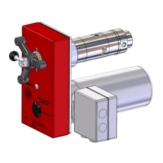
QUICK START: HART WIRING
A6 VALVE ACTUATOR
AM7E FLOW CONTROL VALVE
A & H Enterprises, Inc.
11812 NE 116th Street
Kirkland, WA 98034 USA
www.amflow.com
AMFLOW
with
00000329-0900-014 * Rev. B, 06/16
+425.883.4040
TEL:
+425.823.1962
FAX:
ah@amflow.com
EMAIL:
®
Page 1 of 21
Advertisement

Related Manuals for AMFLOW A6

Summary of Contents for AMFLOW A6
- Page 1 FAX: Amflow ® www.amflow.com ah@amflow.com EMAIL: QUICK START: HART WIRING AMFLOW ® A6 VALVE ACTUATOR with AM7E FLOW CONTROL VALVE Copyright 2016 A & H Enterprises., Inc. © 00000329-0900-014 * Rev. B, 06/16 Page 1 of 21 All rights reserved...
-
Page 2: Table Of Contents
A6 Quick Start: Hart AMFLOW ® CONTENTS Contents 1. What is Included 2. Installation: Actuator 3. Installation: Valve 4. Electrical Set-Up: Actuator 5. Wiring: Hart 6. Optional Ethernet Set-Up 7. Connection to Device 8. Caution Information 9. Safety Information 10. Suport 11. -
Page 3: What Is Included
A6 Quick Start: Hart AMFLOW ® WHAT IS INCLUDED Amflow ® What is included with your product? ☐ ACTUATOR: A6 Actuator Adjustment Handle Adjustment Handle Mounting Screw and Lock Washer Installation Manual & Service Manual Copyright 2016 A &... -
Page 4: Installation: Actuator
A6 Quick Start: Hart AMFLOW ® INSTALLATION Installation: Actuator Step 1 Cut-out panel for mounting per instructions in Installation Manual. Copyright 2016 A & H Enterprises, Inc. © 00000329-0900-014 * Rev. B, 06/16 Page 4 of 21 All rights reserved... - Page 5 A6 Quick Start: Hart AMFLOW ® INSTALLATION Step 2 Attach actuator base plate assembly to front of panel. Step 3 Mount actuator to base plate assembly using M6x16 SHCS. Copyright 2016 A & H Enterprises, Inc. © 00000329-0900-014 * Rev. B, 06/16...
- Page 6 A6 Quick Start: Hart AMFLOW ® INSTALLATION Step 4 Prior to installing valve, confirm handle is in manual position. MANUAL MODE AUTOMATION MODE (Handle at Front) (Handle at Side) Copyright 2016 A & H Enterprises, Inc. © 00000329-0900-014 * Rev. B, 06/16...
-
Page 7: Installation: Valve
A6 Quick Start: Hart AMFLOW ® INSTALLATION Installation: Valve Step 1 Place FLANGE ADAPTOR onto VALVE STEM prior to installation. FLANGE ADAPTOR VALVE ADAPTOR LINK Step 2 Insert VALVE ADAPTOR LINK into FLANGE ADAPTOR. Place valve into BEARNG HOUSING. - Page 8 A6 Quick Start: Hart AMFLOW ® INSTALLATION Step 3 While valve is being inserted into BEARING HOUSING; rotate valve to align VALVE ADAPTOR LINK while handle is in manual mode. Step 4 Once properly aligned and engaged, tighten three (3) SETSCREWS to lock valve in place.
- Page 9 A6 Quick Start: Hart AMFLOW ® INSTALLATION Controls: Applicable to AM7E-001 Valve Only There are two controls used to operate the AM7E-001 flow control valve: The first control is the SWITCH by which the operator can select a high or low flow range.
-
Page 10: Electrical Set-Up: Actuator
A6 Quick Start: Hart AMFLOW ® WIRING ELECTRICAL SET-UP: Actuator Board Both power cable and HART cable must be connected. First, remove the electrical panel cover by loosening the four (4) screws on the electrical box and removing the panel. Be careful not to lose the screws. - Page 11 Due to the wide variety of HART controllers on today’s market, it is necessary to consult the manuals of the HART controller. This ensures proper installation of the DD file and commissioning of the Amflow Actuator. A DD file is provided by Amflow upon delivery of an Amflow Actuator. Step 1: ...
-
Page 12: Connection To Device
A6 Quick Start: Hart AMFLOW ® COMMUNICATIONS ETHERNET COMMUNICATION SET-UP: OPTIONAL Additionally, if an Ethernet connection is desired a cable must be connected according to the diagram. 1. Connect TX + to Terminal Block 13. 3. Connect TX - to Terminal Block 14. - Page 13 A6 Quick Start: Hart AMFLOW ® COMMUNICATIONS Cat 5 or 6 Cable DHCP SERVER Cat 5 or 6 Cable Computer FOR FULL ACTUATOR INSTALLATION INSTRUCTIONS REFERENCE INSTALLATION & OPERATION MANUAL Copyright 2016 A & H Enterprises, Inc. © 00000329-0900-014 * Rev. B, 06/16...
- Page 14 A6 Quick Start: Hart AMFLOW ® COMMUNICATIONS AME AND ASSWORD The user name and password for main web page: User Name = admin Password = a2admin ROWSER UPPORT This unit has been fully tested on the Firefox web browser in Windows 7.
- Page 15 A6 Quick Start: Hart AMFLOW ® FLOWMETER Copyright 2016 A & H Enterprises, Inc. © 00000329-0900-014 * Rev. B, 06/16 Page 15 of 21 All rights reserved...
- Page 16 A6 Quick Start: Hart AMFLOW ® FLOWMETER Copyright 2016 A & H Enterprises, Inc. © 00000329-0900-014 * Rev. B, 06/16 Page 16 of 21 All rights reserved...
- Page 17 A6 Quick Start: Hart AMFLOW ® CAUTION Caution CAUTION IMPROPER INSTALLATION AND START-UP MAY CAUSE DAMAGE VALVE INSTALLATION RECOMMENDATION valve should be connected to a “return to ® The purge port on an Amflow tank line” with a needle valve. This aids in the following: ...
- Page 18 A6 Quick Start: Hart AMFLOW ® CAUTION PROCEED with CAUTION This is very important, especially at high system pressures to prevent potential damage to seals and other internal components of valve. Step 4 VERY SLOWLY open Outlet Isolation Valve.
-
Page 19: Safety Information
A6 Quick Start: Hart AMFLOW ® SAFETY Safety SAFETY INFORMATION Usage Use products only within range of pressure and temperature conditions indicated on product data sheet. Do not use with chemicals which are incompatible with 316SS or with seal materials. - Page 20 AMFLOW ® SUPPORT Support To order Amflow® products, spare parts or to receive assistance contact: ® A & H Enterprises, Inc. (Amflow +425.883.4040 ADDRESS CORRESPONDENCE TO: A & H Enterprises, Inc. 11812 NE 116 Street Kirkland, WA. 98033 E-mail: ah@amflow.com Fax: +425.823.1962...
-
Page 21: Representatives
A6 Quick Start: Hart AMFLOW ® REPRESENTATIVES Representatives ® AMFLOW NORGE Norway, Sweden, Denmark, Netherlands, Germany, U.K., Italy Prinsens vei 12 4315 Sandnes Norway Telephone: +47.922.19.656 Fax: +47.520.00.591 E-mail: leif.egil.pettersen@amflow.no AMFLOW CONTROLS ASIA SDN. BHD. Malaysia, Indonesia, Singapore, India, Thailand, Vietnam No.
Need help?
Do you have a question about the A6 and is the answer not in the manual?
Questions and answers