Table of Contents
Advertisement
Quick Links
Using the O-Lynx Radio system for the first time.
An O-Lynx radio system will consist of the
items shown in Figure 1. If you are using
the system for the first time then having a
practise setup before the event will be
worthwhile to get to know how the system
operates.
The radios may arrive without the
antennas fitted to make shipping easier. Fit
these now by screwing into the top of the
radios until finger tight. Ideally the
antennas should be kept fitted to the radio
Figure 1: O-Lynx Radio Kit
units and not removed in between use.
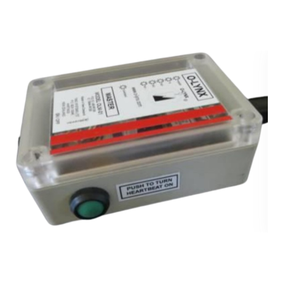
Locate the "Master" radio. This can be identified by "MASTER" written on the label and also by the
"Heartbeat" switch on the right side of the case. This radio is used at the event centre as all other
radios are setup to send the punch information back to
the "Master". A 5 metre USB cable is supplied along
master to connect to a computer.
Switch on the Master now by pushing the button at the
base of the radio. Note the startup sequence that
applies to all O-Lynx radios. The 5 LED's will light up
from the bottom, then the unit will beep and the 5
LED's will show the battery level for about 1 second.
For example, fully charged will be indicated by all 5
LED's on.
Figure 2: Master radio
Once the startup sequence has finished, the LED's take
on their normal roles as indicated on the units' label.
The top LED will flash every 3 secs to indicate the unit is powered up.
The "Heartbeat" switch turns on when pressed in. Try this now. This will light up the second from
top LED every 3 seconds to indicate a heartbeat message is being sent out to all radios. This is used
to check range when setting out the "Control" radios at an event.
The "Control" radios are used out on the map and are usually attached to Sportident BSM-7 stations
to send the punches at this station back to the "Master" radio. They can also be used stand-alone as
repeater type radios to extend the range of the O-Lynx system. Note that all "Control" radios will act
as repeaters, whether or not they are attached to Sportident stations and no programming or setup
is needed to enable this.
Advertisement
Table of Contents

Summary of Contents for O-Lynx Radio Kit
- Page 1 “Master” radio. They can also be used stand-alone as repeater type radios to extend the range of the O-Lynx system. Note that all “Control” radios will act as repeaters, whether or not they are attached to Sportident stations and no programming or setup...
- Page 2 Installing the driver for the Master connection. The serial to USB cable used to connect the “Master” radio requires a software driver to be installed on the PC. This may be supplied with the O-Lynx software or the latest version can be downloaded from…...
- Page 3 You should now have 3 icons on your desktop for the O-Lynx software and an icon for the Nexus Database Server. As the Nexus Database Server will be set to start when the computer is switched on you should not need this icon unless the server is exited for some reason.
- Page 4 SI card. When doing so the TX LED on the “Control” radio should light up followed by the RX LED on the “Master”. The punch information with the SI card number, time of punch and “Unknown” as the competitors name should also show up on the status bar of the O-Lynx Event screen.
-
Page 5: Setting Up Additional Computers
The secondary computers will just need the Results.exe and Tools .exe program files. It also doesn't matter where ( what folder on the PC ) they go in. For easy setup use the O-Lynx install program to do this, but during the installation, untick the install database server and files question when asked as these are not needed. -
Page 6: Appendix A: Setting Up The Sportident Stations For Use With Radio Controls
Appendix A: Setting up the Sportident stations for use with radio controls. The course planner has given controls specific numbers. These have been printed on the maps, control descriptions and setup in the computer system. Therefore when replacing an existing control with a radio controls, the same number must first be programmed into the replacement control. - Page 7 Start the SIConfig program and you should see a screen as shown below. a. Change from “remote” to “direct” if the SI control is plugged directly into the PC. Leave on “remote” if using a coupling stick. b. Press read to get the stations existing details. c.
- Page 8 Tick the "Extended Protocol" box to enable the larger messages that allow for higher control numbers. Because a limit needed to be set somewhere, O-Lynx currently expects control numbers to be below 400.
-
Page 9: Appendix B: Mounting The O-Lynx Radios
The finished stand is shown below along with an O-Lynx radio. - Page 10 While the output power of O-Lynx controls is considerably less than that from a standard cellphone, users in the US should note the following information HAS to be advised. The O-Lynx brackets took this regulation into account when they were designed.
-
Page 11: Appendix C: O-Lynx Battery Charging And Monitoring
USB port when connected. This uses a low power charging circuit to ensure it is compatible with all USB ports. O-Lynx radios with higher capacity batteries have also been used on adventure races. These provide the ability to run continuously for at least 48 hours. -
Page 12: Appendix D: Setting The Master Address For The Control Radios
Panel. To teach the radios the Master Address, set up the Control radios along with the Master radio and turn them all on. Also connect the master to the computer running the O-Lynx Event software as shown above. - Page 13 The Master Address is also usually identified on a label on the left hand side of the Master case. If no address showed up in the box next to the “Set Master Address” button, enter this address in this box now. E.g. this photo shows the Master Address as 043F55 Now follow these steps to teach the radios the correct Master Address.
-
Page 14: Appendix E: Replacing The Sportident Bsm7 Rs232 Connectors
Appendix E: Replacing the Sportident BSM7 RS232 Connectors. O-Lynx radios use a locking waterproof connector for connecting securely to the Sportident base stations. This means the D type plugs that come standard on the BSM7 units must be replaced prior to using with O-Lynx. - Page 15 Step 5 : Strip the insulation from the last 2mm of the wires and tin with a soldering iron. Step 6 : Slide the connector parts onto the cable in the order shown. Step 7 : Tin the pins of the plug. Step 8 : Solder the wires onto the plug while being careful not to use to much solder and create bridges between the pins.
-
Page 16: Appendix F: Making O-Lynx To Serial Port Adapters
In the event that the BSM7 Stations still need to be connected to a serial port e.g. for programming directly via SI-Config, an adapter is used to convert the O-Lynx waterproof connector back into the standard 9-way serial plug. One of these adapters is normally supplied as part of the starter kit.
Need help?
Do you have a question about the Radio Kit and is the answer not in the manual?
Questions and answers