Table of Contents
Advertisement
Quick Links
Advertisement
Table of Contents

Summary of Contents for JIB MJ10-1300E
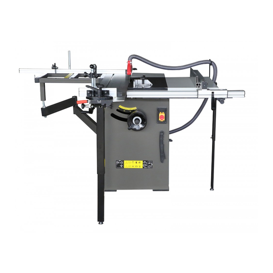
- Page 1 Instruction Manual Sliding Table Saw Model No.: MJ10-1300E / MJ10-1600E...
-
Page 2: Safety Instructions For Power Tools
For Your Own Safety, Read Instruction Manual Before Operating This Equipment The purpose of safety symbols is to attract your attention to possible hazardous conditions. This manual uses a series of symbols and signal words which are intended to convey the level of importance of the safety messages. - Page 3 15. USE RECOMMENDED ACCESSORIES. Consult the instruction manual for recommended accessories. The use of improper accessories may cause risk of injury. 16. REDUCE THE RISK OF UNINTENTIONAL STARTING. On machines with magnetic contact starting switches there is a risk of starting if the machine is bumped or jarred. Always disconnect from power source before adjusting or servicing.
-
Page 4: Site Considerations
No list of safety guidelines can be complete. Every shop environment is different. Always consider safety first, as it applies to your individual working conditions. Use this and other machinery with caution and respect. Failure to do so could result in serious personal injury, damage to equipment, or poor work results. -
Page 5: Floor Load
exceed 50% at a maximum temperature of +40 ˚C, higher relative humidity may be permitted at lower temperature (e. g. 90%@ 20 ˚C). Floor Load This machine represents a moderately large weight load in a small footprint. Most commercial shop floors will be adequate for the weight of the machine. - Page 6 A. Crosscut Table-Provides a wide, stable platform for supporting full-size panels during crosscutting operations. B. Flip Stops-Used for quick measurements for crosscutting. C. Crosscut Fence-Used during crosscutting operations. Features a scale and multiple flip-style stopblocks for precise, repeatable crosscutting operations. E.
- Page 7 R. Support Leg-Provides the support for the extension table. S. Main Blade Angle Lock Knob-Secures the angle of main blade. T. Hold Down w/Mitre Gauge-Holds the work-piece for sliding or mitre cutting. U. Riving Knife-Maintains kerf during cutting operations. This function is crucial to preventing kickback caused by the kerf closing behind the blade.
-
Page 8: Moving & Placing Saw Base Unit
Many of the solvents commonly used to clean machinery can be toxic when inhaled or ingested. Always work in well ventilated areas far from potential ignition sources when dealing with solvents. Use care when disposing of waste rags and towels to be sure they do not create fire or environmental hazards. - Page 9 Attach the extension table to major table with 4-M8x20 hex head screws/ washers. Center the extension table over the edges and tap it. Check the surface alignment.
- Page 10 Install the sub-support ( model MJ10-1300E / MJ10-1600E Attach the front sub-support to saw base unit and Tight it with 4-M8x25 allen screws w/spring washers. 2. Attach the front sub-support to main saw base on same way. Align the front sub-support. Rear sub-support and the main saw base on the same level.
- Page 11 The support needs further adjustment. Install the Sliding panel assembly 1 .Place 2 sets of star-type screws (include 8mm washer, insert, screw guide) into the lower slot of sliding panel carrier. 2.Put the sliding panel assembly onto the sliding panel supports, and lay two star-type screws. 3.Tighten two star-type screws.
- Page 12 Adjust the sliding panel level 1 . Place a level rule (cross cut fence) on to major table and sliding panel. 2.Loosen 4-M8x25 hex screws(A) , adjust the M8x40 hex screw(B) to adjust the sliding panel level. 3.Then re-tighten 4-M8x25 hex screws (A). 4.To fine adjust, using 3 mm "L"...
- Page 13 Install the dust port Place the dust port onto the bottom of rear panel, tighten it with 4 M6x12 pan head screws washers and nuts (nuts inside stand). Install the blade guard The riving knife cuts 3 slot for different blade size, and the blade guard mounts to the 254 slot. Install the dust hose support To install the dust hose support onto the rear portion of steel p l a t e e x t e n s i o n t a b l e w i t h 2 M6x20 hex head screws washers and nuts( nuts under the table).
-
Page 14: Replacement And Adjustment
Install dust hoses 1. Install the 2" dust hose onto the blade guard with 2" hose clamp. 2. Put the 2" dust hose onto dust hose support, keep free with the working table. 3. Another end of 2" dust hose clamps to the main dust port on the bottom of rear panel. Install 4"... - Page 15 Disconnect the saw from the power source! The riving knife is carved with different blade size, just put the carved line under table. The center carriage bolt is mounted in a horizontal slot, so the riving knife can move far or near the main blade.
-
Page 16: Rip Cutting
panel and your mark on the blade as shown in Fig 29. 5. Move the other end of the sliding panel in front of the blade and measure the gap. If the gap is the same on both sides, then the sliding panel is already parallel with the main blade. If the gap on one side is different than the other, then continue with step6. - Page 17 lighter boards are easier to slide across the stationary cast iron table surface to the right of the saw blade. Determine which cutting operation will be best suited for the workpiece to be ripped. To use the sliding table, read the instructions titled "Rip cutting with the sliding panel." To use the machine as a traditional table saw, skip ahead to "Rip cutting using the traditional table saw technique."...
- Page 18 size panels. With the crosscut fence mounted in the rear position, this machine also has the capability of crosscutting smaller panels. This machine has the capability of crosscutting workpieces while using the hold down w/mitre gauge . Lastly, this machine has the capability of crosscutting workpieces while using the rip fence as a cut-off gauge. Determine which cutting operation will be best suited for the workpiece to be crosscut.
- Page 19 2. Install the crosscut fence in the forward guide pin holes and lock it in place. Note First, drop the crosscut fence into the forward guide pin hole, turn the "Z" lock plate to align the fence, then tighten the knurled nut. 3.
-
Page 20: Miter Cutting
the knurled nut. 3. Position the rip fence to the desired width-of-cut. 4. Load the workpiece onto the table saw. 5. Mount the hold down arm onto the stud and lock the work-piece in place. 6. Once all the necessary safety precautions have been taken, perform the cutting operation. Miter Cutting The cross cut table built two scales for forward and rear mount fence to perform mitre cut. -
Page 21: Maintenance
3.Position the flip stop according to the length of the workpiece you want to cut off to the left of the blade. Note If the workpiece extends to the left of the saw blade more than 1200mm, then the crosscut fence slide needs to be extended. -
Page 22: Main Switch
Worn switch. Worn or damaged blade. Worn or damaged blade guard. V-Belts To ensure optimum power transmission from the motor to the blade and to the hydraulic pump, the V-belts must be in good condition (free from cracks, fraying and wear) and operate under proper tension. Check the V- belts at least every 3 months;... -
Page 24: Parts List & Diagrams
PARTS LIST & DIAGRAMS Parts List Diagram A Description Description Allen screw M6x12 Cover, switch box Washer 6mm Pan head screw M4x12 Right panel, saw base Main switch Saw base frame Taping screw ST4.2x20 Washer 5mm Knee touch plate Knee touch plate Internal guard Taping screw ST4.2x20 Knee touch plate... - Page 25 Parts List Diagram B cont... Description End cap, fence Allen screw M5x16 Disc, hold down Star-type knob, hold down Arm, hold down Circle ring 8mm Pin, hold down spring, hold down Stud, hold down Circle ring 12mm Eccentric, hold down Handle, hold down Handle knob, hold down Parts List Diagram C...
- Page 26 Parts List Diagram C cont... Description Description C2-1 Lock bolt, guard Washer C2-2 Half, blade guard Hex head screw M10X25 C2-3 Half, blade guard Chip house C2-4 Lock washer 8mm Hose clamp 50mm C2-5 Knuried nut Dust removing tube 50 Taping screw ST4.2X10 C2-6 Flat key 4×16...
- Page 27 Parts List Diagram D Description Description Fence "L" shape T-nut M5 Carriage screw M6x50 Washer 5mm Cap screw Pan head screw M5x10 Bush Set screw M6x6 Fine adjusting handle Fence Coil spring, fine adjust Flat pad 6 T type lock handle Eccentric arbor Sunk head screw M6x12 Frame, fine adjust gear...
- Page 28 Parts List Diagram E Description Description Big flat mat 16 Scale, cross cut table End cap, swing arm Scale, cross cut table Shaft, swing arm End cap, cross cut table Inner six corner tight nailM8×20 T-block Swing arm Flat washer M8 Block Wing nut M8 Hex screw M6x35...
Need help?
Do you have a question about the MJ10-1300E and is the answer not in the manual?
Questions and answers