Table of Contents
Advertisement
Quick Links
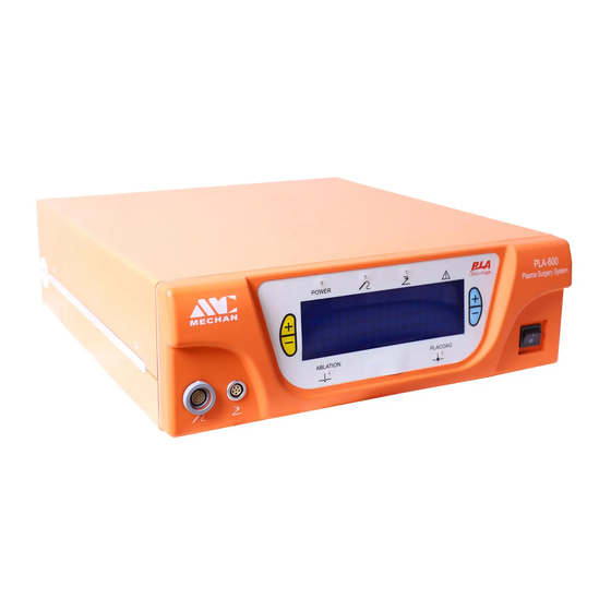
Plasma Surgery System
PLA-600 User Manual
Manufacturer for: Chengdu Mechan Electronic Technology Co., Ltd
No. 11, District 9,
Road, Chengdu Straits Science&Tech Industrial Development Park,
Wenjiang District, Chengdu, China
Customer Service: 400 666 0366
Email: sales@mechan.com.cn
Well Kang Limeted
The Black Church,St.Mary's
Place,Dublin 7,Ireland
REF
PLA-600
Version 01
2013.12
Huayin Industrial Harbor, No.618, West Kelin
DOC. MEUM-131205700. Version 01
Advertisement
Table of Contents

Summary of Contents for Mechan PLA-600
- Page 1 Plasma Surgery System PLA-600 User Manual Manufacturer for: Chengdu Mechan Electronic Technology Co., Ltd No. 11, District 9, Huayin Industrial Harbor, No.618, West Kelin Road, Chengdu Straits Science&Tech Industrial Development Park, Wenjiang District, Chengdu, China Customer Service: 400 666 0366 Email: sales@mechan.com.cn...
- Page 2 Proprietary Information Notice This document contains information proprietary to Chengdu Mechan Electronic Technology Co., Ltd, with all rights reserved. No part of this document may be used, reproduced, transmitted, processed or recorded by any means or form, electronic, mechanical, photographic or otherwise, nor to be released to any third party without the prior written consent of Chengdu Mechan Electronic Technology Co., Ltd.
-
Page 3: Table Of Contents
Table of Contents ATTENTION------------------------ -----------------------------------------------------------------V SECTION 1 INTRODUCTION------------------------------------------------------------------------1-1 1.1 PURPOSE OF THIS MANUAL---------------------------------------------------------------------1 1.2 MANUAL ORGANIZATION------------------------------------------------------------------------1 1.3 MANUAL CONVENTIONS-------------------------------------------------------------------------1 SECTION 2 SYSTEM APPLICATIONS--------------------------------------------------------------2-2 2.1 GENERAL CONFIGURATION OF SYSTEM----------------------------------------------------2 2.2 CLINICAL INDICATION AND CONTRAINDICATION---------------------------------------2 2.2.1 Indication--------------------------------------------------------------------------------2 2.2.2 Contraindication---------------------------------------------------------------------------2 SECTION 3 SYSTEM SKETCH--------------------------------------------------------------------------------3-7 3.1 CONNECTION GRAPH------------------------------------------------------------------------------3 3.2 WORKING PRINCIPLE---------------------------------------------------------------------------3-4 3.2.1 Principle------------------------------------------------------------------------------------3... - Page 4 5.2.2 Gear Position (Power Output Value) Adjustment----------------------------------------9 5.3 VOLTAGE OUTPUT--------------------------------------------------------------------------9 5.4 SYSTEM PREPARATIONS---------------------------------------------------------------------9-10 5.5 SYSTEM SHUT DOWN---------------------------------------------------------------------------10 5.6 TRANSPORTATION AND STORAGE----------------------------------------------------------10 5.6.1 Transportation--------------------------------------------------------------------------------10 5.6.2 Storage----------------------------------------------------------------------------------------10 5.7 REGULATIONS ON SCRAPED EQUIPMENT------------------------------------------------10 SECTION 6 SYSTEM SPECIFICATIONS-------------------------------------------------------------------11 6.1 TECHNICAL SPECIFCIATION------------------------------------------------------------------11 6.1.1 Treatment Handle ---------------------------------------------------------------------------11 6.1.2 Host Device----------------------------------------------------------------------------------11 6.1.3 Power Output --------------------------------------------------------------------------------11 6.1.4 Dimensions of Host Device----------------------------------------------------------------11...
-
Page 5: Attention
Attention 1. This unit is approved after test, and testified as according with the regulations on medical devices of GB9706.1-2007 and GB9706.4-2009. The regulations are providing suitable protection from harmful influence during installation. This unit generates and uses plasma energy. If not installed suitably, it may cause harmful influence on the surrounding devices. -
Page 6: Section 1 Introduction
Purpose of This Manual This document provides information in details in regards to Plasma Treatment System (Urology Plasma Ablation System) PLA-600 Tabletop Version. It mainly contains the general information, installation and checkout instructions, and technical specifications of the system. Manual Organizations... -
Page 7: Section 2 System Applications
System Application General Configuration of System This unit is a plasma electrosurgical system with bipolar and multi polar functions. It’s designed for Urology surgeries. Mainly containing the parts as follows: 1). One tabletop generator device 2). One reusable and non-sterile power supply cable. 3). -
Page 8: Section 3 System Sketch
Section 3 System Sketch Connection Graph: Host Device Power Supply Cable Footswitch Plate Footswitch for ABLATION Footswitch for PLACOAG Treatment Handle 7/8. Plasma Probe Socket for Footswitch Socket for Treatment Handle Working Principles 3.2.1 Principle: This unit can transmit energy to the electrode part at the far end of treatment probe. Electricity flows between working electrode and circuit electrode, and only generate local energy field. -
Page 9: Drawing Of Principle
functions will vary if the given voltage between the working electrode and target tissues is lower. In this case, the electric field is lower than the value required for forming plasma, and resistance heat at the tissues is generated. This model is used when stronger heat effect is required, e.g. for coagulation of blood vessel or other vessel tissues. -
Page 10: System Structures And Configuration Introduction
System Structures and Configuration Introduction 3.3.1 Instructions of Different Signs --- refers to the Mark of Flow Control Unit --- refers to the Mark of Protection Class (ours is CF type). --- refers to Footswitch Connection --- refers to Volume Adjustment at the Host Machine. --- refers to Power Supply Turned On --- refers to Power Supply Turned Off --- Follow instructions for use... - Page 11 3.3.2 Control Keys and Marking of the Host Device (Shown with Graph) Manufacturer Logo Four Pads Socket for Footswitch Socket for Treatment Handle DOC. MEUM-131205700. Version 01...
-
Page 12: Identification Of Working And Warning
Power Switch Model No. of the Unit: PLA-600 Display Light for Treatment Probe Connection. Green when connected and Red when not connected. Display Light for Footswitch Connection. Green when connected and Red when not connected. ABLATION Display to show the preset ABLATION output value in tow digits. -
Page 13: Section 4 Unpacking, Installation And Checkout
Section 4 Unpacking, Installation and Checkout Unpacking: To confirm the unit, accessories and all print materials arrive in a complete and safe status. Any damage found, to keep all needful materials and contact the after sales service department for arrangement. Installation and Checkout Put the device in proper and stable way and move or handle it carefully to avoid the cables outside the host machine from scratch. -
Page 14: Section 5 Instruction Of Use
Section 5 Instructions of Use Requirement on Operators: Operators should be experienced in electrosurgical surgeries, should get to know the latest progress ofUrology surgeries. General System Operations 5.2.1 Footswitch: To activate the host device functions. It has two functions as below: To activate ABLATION functions: Press the yellow switch for ABLATION to activate the ABLATION mode. -
Page 15: System Shut Down
adjust the gear position of output for the corresponding model, so as to ensure the surgery completed in a safe and effective way. System Shut Down: Press the power supply switch to the position of “ ”, and wait for below 5 seconds until all lights at the host device are off. -
Page 16: Section 6 System Specifications
Section 6 System Specifications Technical Specifications 6.1.1 Treatment Handle: Length -------------------------------------------------------------------------------------------------------------2.0m; Cleanness way ----------------------------------------------------------------------------------- anhydrous ethanol; 6.1.2 Host Device: Power Input ---------------------------------------------------------------------------------------------------- 700VA; Voltage ------------------------------------------------------------------------198-242VAC 50Hz /110 VAC60Hz; Frequency ---------------------------------------------------------------------------------------------- 50Hz or 60Hz; Fuse Type ---------------------------------------------------------------------------------------------- F5A L250VAC; 6.1.3 Power Output General Frequency ------------------------------------------------------------------------------------------ 100KHz;... -
Page 17: Security Statement
6.2.2 Security Statement: This unit meets the requirements of Term 19.1, 19.2, and 19.3 of GB9706.1-2007 and GB9706.4-2009. Leakage electricity (Grounding)--------------------------------------------------------------------------- 200A; Leakage electricity (Patients)-------------------------------------------------------------------------------- 20A; The unit can’ be used in flammable anesthetic environment. DOC. MEUM-131205700. Version 01... -
Page 18: Section 7 Emc Tables
Guidance and manufacturer´s declaration – electromagnetic emission The model PLA-600 is intended for use in the electromagnetic environment specified below. Thecustomer or the user of the model PLA-600 should assure that it is used in such an environment. Emissions test Compliance Electromagnetic environment –... - Page 19 SYSTEMSGuidance and manufacturer´s declaration – electromagnetic immunity The Model PLA-600 are intended for use in the electromagnetic environment specified below. Thecustomer or the user of the Model PLA-600 should assure that it is used in such an environment. Immunity test...
- Page 20 Guidance and manufacturer’s declaration – electromagnetic immunity The PLA-600 is intended for use in the electromagnetic environment specified below. The customer or the user of the PLA-600 should assure that it is used in such an environment. Immunitytest IEC 60601...
- Page 21 SUPPORTINGRecommended separation distances between portable and mobile RF communications equipment and the model PLA-600 The Model PLA-600 is intended for use in an electromagnetic environment in which radiated RF disturbances are controlled. The customer or the user ofthe Model PLA-600 can help prevent...
Need help?
Do you have a question about the PLA-600 and is the answer not in the manual?
Questions and answers