
Summary of Contents for ACCEL DFI Engine Analyzer Series
- Page 1 Engine Analyzer Series Wideband Oxygen Sensor Installation and Instruction Manual For DFI part numbers: 77062, 77062N, 77062S, 77063 INSTR 77062 2007-10-25...
-
Page 2: Table Of Contents
Table of Contents Introduction ....................2 Installation and configuration ..............3 Wiring Harness Connections ................ 4 Configuring the controller with the DFI Gen 7+ system ....... 7 Installing and Connecting the Air/Fuel Ratio Gauge ........8 Harness Schematic and Pinout Chart – 1 Channel ........9 Harness Schematic and Pinout Chart –... -
Page 3: Introduction
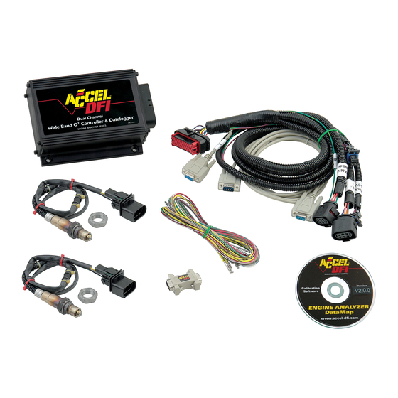
All Engine Analyzer Series kits include integrated Data Logging functions, and are available with a host of options and configurations to suit virtually any application. The following is a list of available part numbers in the Engine Analyzer Series along with the associated parts and configurations for each number: 77062 –... -
Page 4: Installation And Configuration
Installation and configuration Read over this entire document before beginning installation! Securely mount the controller to a location within 36 inches of the oxygen sensor location. The controller may be located inside the car or in the engine compartment. The controller unit is water-resistant, but it is not waterproof. If you are mounting the controller in the engine compartment, select a location with minimal exposure to water as a safeguard. -
Page 5: Wiring Harness Connections
Accel DFI dealer. The part number for this kit is 77063S. If you are connecting the control module to an Accel DFI Generation 7+ system, the 4 pin square male connector in the main harness will have a corresponding female connector in the Generation 7 system harness labeled as “HEGO”. - Page 6 Diagram A – EA series module used with Accel DFI Gen 7+ Engine Management System Diagram A1 – EA series module shown with optional dual wideband sensors...
- Page 7 Diagram B –EA series module used as a standalone air/fuel ratio meter Diagram C – EA series module used with engine management system other than Accel DFI...
-
Page 8: Configuring The Controller With The Dfi Gen 7+ System
Configuring the controller with the DFI Gen 7+ system Once the Engine Analyzer Series controller is properly connected to your Gen 7+ system per the above diagram, you must make a few quick changes to the configuration of your Gen 7+ ECM for it to operate properly. Refer to Diagram D and perform the following steps: Run the CalMap software program and go online with your ECM. -
Page 9: Installing And Connecting The Air/Fuel Ratio Gauge
The red power wire should be connected to a switched +12V source. The Accel DFI air/fuel ratio gauge is designed specifically to operate with this controller. The multi-color LED sweep display around the perimeter of the gauge face is specially calibrated to provide instant feedback to the driver by changing colors as the air/fuel ratio range varies. -
Page 10: Harness Schematic And Pinout Chart - 1 Channel
Harness Schematic and Pinout Chart – 1 Channel... -
Page 11: Harness Schematic And Pinout Chart - 2 Channel
Harness Schematic and Pinout Chart – 2 Channel... -
Page 12: Populating Additional Wires In The Harness Header
Populating Additional Wires in the Harness Header Release the two tabs on the sides of the connector retainer. Slide the wire retainer away from the connector. It does not need to be removed. - Page 13 Insert the wire into the proper location on the connecter. The wire pin locations are marked on the back and sides of the connector. Push the wire retainer back down in order to lock the wires into place.
-
Page 14: Wire List
This component is installed in the sensor by the sensor manufacturer to calibrate the sensor and ensure accuracy. It is not installed by Accel DFI. Tampering with this calibration resistor may result in sensor inaccuracy, poor engine performance, or engine damage! RPM Input –... - Page 15 +12V source for the controller to operate. If you are NOT connecting this controller to an Accel DFI Gen 7+ Engine Management system, it is recommended to install a 30-amp fuse on this line for short circuit protection. Note that on some models, this input must remain powered until data is read from the integrated internal data logger or else the stored data will be lost.
- Page 16 Note: All input and output drivers are active low. For example, in order to trigger data logging, the input wire (AuxIn1, Pin 7, Color: Green with Yellow trace) will be activated by switching the input wire to a ground source. Similarly, any output wire should be connected to the ground trigger of a relay for proper operation.
-
Page 17: Pcb-Mounted Dip Switch Chart And Function List
PCB-Mounted DIP Switch Chart and Function List There is a Dipswitch mounted on the circuit board of the Engine Analyzer that can be used to quickly configure the sensor for customized operation. The Dipswitch is located at the back of the circuit board, and can be easily accessed by removing the rear endplate of the enclosure. -
Page 18: Connecting An Older Ntk-Only System To A Bosch Lsu 4.2 Sensor
Connecting an Older NTK-Only System to a Bosch LSU 4.2 Sensor THIS PROCEDURE ONLY APPLIES TO REVISION A ENGINE ANALYZER MODELS WITH FIRMWARE VERSION 1.0.2, AND REVISION ‘A’ WIRING HARNESSES HAVING BLACK/WHITE WIRES CONNECTED TO HEADER PIN #24. DATAMAP SOFTWARE VERSION 1.0.3 OR HIGHER IS REQUIRED TO SELECT OXYGEN SENSOR TYPE(S). -
Page 19: The Engine Analyzer Integrated Data Logger
The Engine Analyzer Integrated Data Logger The Engine Analyzer has an integrated Data Logging System that can store information gathered internally through the Engine Analyzer controller as well as information from external devices that may be connected to it – like an ACCEL/DFI Generation 7+ ECM. -
Page 20: Engine Analyzer Monitoring
Engine Analyzer Monitoring The DataMap software’s main screen provides a monitoring and control interface to your Engine Analyzer. Air:Fuel Ratio, Engine Speed, Vehicle Speed, Ignition Voltage, and several other parameters are easily read from the real-time readouts. The following is a quick description of the way data values are displayed on the screen. Stripchart: This is an electrical simulation of a paper stripchart recorder commonly used for data analysis. - Page 21 Input/Output Status Indicators: The current state of each input and output line on the Engine Analyzer is represented by a virtual LED on the bottom of the screen. The LED is lit RED when I/O line is active, and shown as black when the I/O state is not active. Data Logger Status: The number of stored logging sessions, and total number of data samples are shown in the center of the screen.
-
Page 22: Data Logger Operation
Data Logger Operation The Data Logger can be used to record internal data generated by the Engine Analyzer and the optional data inputs built into it. Basic logger operation will allow you to record the following 4 or 5 internal channels: Engine Analyzer Air-to-Fuel Ratio(s) –... - Page 23 looped recording mode can be enabled which will continuously store the last several minutes of data inside the logger. The length of recording time depends on the sample rate selected. When recording Generation 7+ ECM data, the logger will continuously retain over 20 minutes of recorded data. When data is stored in the Engine Analyzer, the main screen of the DataMap software will show a Number of Runs of at least 1, and the actual number of data samples contained in the logger memory.
-
Page 24: Data Logger And Single Channel I/O Configuration
Data Logger and Single Channel I/O Configuration The DataMap software Configuration Screen is used to configure the internal Data Logger and all associated external input/output functions within the Single Channel Engine Analyzer models. Press the CTRL + C keys, or select File->Configure Data Logger to see the Single Channel Configuration screen. - Page 25 data logging will occur anytime the Data Logging Input (Auxiliary Input #1) is connected to an electrical ground source. Logging will stop when the input is disconnected from the electrical ground source. Logger Data Source If your Engine Analyzer is connected to an ACCEL/DFI Generation 7+ ECM, and you want to record internal data values from within the ECM, set this switch to RECORD GEN 7+ ECM DATA.
- Page 26 A:F Data Source When recording Generation 7+ ECM data, this switch controls the source of the Air to Fuel Ratio data channel. Setting this switch to the GEN 7+ ECM position will cause the Data Logger to record the air to fuel ratio from your Generation 7+ ECM. Setting this switch to the INTERNAL MEASURED A:F RATIO position will cause the Data Logger to record it’s own internal air to fuel ratio.
- Page 27 RPM Pulses / Crank Revolution This table is used to accurately calculate Engine Speed from the signal seen on the Engine Speed input. Enter the number of trigger events on the Engine Speed input that equates to 1 revolution of the engine. Driveshaft Pulses / Revolution This table is used to accurately calculate Vehicle Speed in Miles Per Hour from the signal seen on the Output Shaft Speed input.
- Page 28 Trigger: The logic in which the enable and disable values are used to satisfy the triggering conditions. NOT USED: The data source in the current row of the table is not used as a triggering parameter for the current output. USED: The data value in the current row is expected to rise to or above the ENABLE value to activate the output, and...
-
Page 29: Auxiliary Output Configuration Examples
Auxiliary Output Configuration Examples Shift Light Output @ 6000 RPM: To configure Auxiliary Output #1 for use as a shift light controller, we need to set up the desired RPM activation window through the DataMap software. For a shift light application, we don’t need to be concerned with the Air:Fuel ratio, vehicle speed, or the state of any hardware input lines. - Page 30 Lean Alarm Output @ Channel 1 13.50 AFR above 3500 RPM: A lean alarm output would be used to signal a lean condition while the vehicle is being driven. Typically, you would only be concerned about a lean condition while the engine is being driven under load, and above a critical Engine Speed value.
-
Page 31: Dual Channel Engine Analyzer I/O Configuration
Dual Channel Engine Analyzer I/O Configuration The Dual Channel Engine Analyzer includes 3 Auxiliary Inputs and 4 Auxiliary Output lines for controlling a wide variety of external functions. Each output is independently configurable and can utilize any input line as its hardware enable switch. -
Page 32: Editing The Voltage Output Vs. Air:fuel Ratio Curve
Editing the Voltage Output vs. Air:Fuel Ratio Curve To edit the 0-5 volt output curve vs. Air:Fuel Ratio, press the Edit Vout vs AFR curve button on either of the I/O configuration screens. Note that this is a Pro-Only feature, and the curve will not be accessible unless you have a USB cable connection to your Engine Analyzer that includes an integrated ACCEL/DFI Professional Powerkey. -
Page 33: Data Analysis Using The Datamap Software
Data Analysis Using the DataMap software The DataMap software includes a 16-channel graph for displaying and analyzing the data recorded by your Engine Analyzer. From the File menu, select File->Graph Log File, or press the Analyze button after reading data from your Engine Analyzer to enter the DataMap Analysis screen. - Page 34 Right Clicking on the Data Graph or selecting Graph Data from the Edit menu brings up the data manipulation menu for the graph. The menu contains the following options: Export Data to CalMap Log File Use this item to create a data log file that can be read by the ACCEL/DFI CalMap Gen 7+ software program.
- Page 35 Show Data for Trace #2 If a second data file is overlaid on the graph, selecting this option will cause the numeric display to show data from Trace #2, the second log file that was overlaid on the analysis graph. Show Difference Data (Trace #2 –...
-
Page 36: Frequently Asked Questions
If the sensor appears to be heavily coated in carbon or oil, it may have failed due to contamination. Contact your Accel DFI Engine Management Installation Center (EMIC) for further information on troubleshooting or replacing the sensor. - Page 37 Accel DFI wideband control systems are measured against state-of-the-art laboratory control systems and are accurate to within .1 AFR across the entire operating range. Also, every system that is shipped from Accel DFI is tested and calibrated on a sophisticated testing machine. The tester calibration, in turn has been validated on an actual running engine under multiple running conditions to ensure accuracy and functionality.
- Page 38 turbocharged engine can cause inaccurate air/fuel ratio readings and lead to premature failure of the sensor.
-
Page 39: Recommended Air/Fuel Ratio Chart
Recommended Air/Fuel Ratio Chart The following chart may be used as a guideline for baseline tuning of your engine. The values specified in this chart should provide reasonably safe starting points when beginning an engine calibration. Once you have tuned your engine to run at or near these values, you can experiment to see how small changes in fueling impact power, economy, and drivability.
Need help?
Do you have a question about the Engine Analyzer Series and is the answer not in the manual?
Questions and answers