Table of Contents
Advertisement
Advertisement
Table of Contents

Summary of Contents for AIR2G2 AIR2G2-336
- Page 1 GT AIRINJECT INC “AIR2G2-336 ” ® OWNER/OPERATOR’S MANUAL...
-
Page 2: Introduction
Remember: AIR IS EVERYTHING TO ANYTHING THAT LIVES®™! INTRODUCTION This owner/operator’s manual will teach you about the operating features of the AIR2G2-336® as well as the maintenance schedules and procedures. You are responsible for safe and proper operation and maintenance of this machine in order to avoid personal injury and/or damage to the machine. -
Page 3: Table Of Contents
MACHINE CONTROLLER PROGRAMMING (PLC) FUNCTION KEYS 30-31 STANDARD OPERATIONS PROCEDURE FOR THE AERATION PROCESS NEUTRAL ARM MECHANISM MAINTENANCE AND STORAGE 33-34 TROUBLESHOOTING WIRING DIAGRAM DRIVE SYSTEM DIAGRAM AIR SYSTEM DIAGRAMS 38-40 STEERING SYSTEM DIAGRAMS PRESSURE BEAM DIAGRAM AIR2G2-336 PARTS LIST 43-51... -
Page 4: Ce Declaration Of Conformity
Jacksonville FL 32254 USA Declares the machine described below complies with applicable essential health and safety requirements of Part 1 and 4 related clauses of Part 3 of Annex 1 of the Machinery Directive 2006/42/EC. Description: AIR2G2® Model Number: AIR2G2®-336 Serial Number: ________________________________________________________________________... -
Page 5: Machine Record Information
MACHINE RECORD INFORMATION This operation and maintenance manual has been prepared for use as a guide. The AIR2G2®-336 has been designed for easy maintenance and simple operation on golf courses and athletic fields. If you have any questions, please feel free to contact your distributor or email us at parts@air2g2.com... -
Page 6: Warranty
-336 that is defective in workmanship or material for a period of two years or twenty-four (24) months from the date of delivery of a new AIR2G2-336 to the original end user. Warranty is VOID if machine has not been run and/or operated OR delivered to final user in over 6 months. -
Page 8: Maintenance Schedule
Use the brush (provided in the toolbox on the machine) to clean out the cylinder mount tubes. Re-mount the cylinders to the base. After each use, it is important to store the AIR2G2®-336 without having air pressure in the system. •... -
Page 9: Important Information
IMPORTANT INFORMATION Please read and understand all enclosed operating manuals before using the AIR2G2®-336. • Pre-check all hoses, nuts, bolts, screws, and probes for tightness prior to operating the machine. • • Understand the operating procedures and controls before use. -
Page 10: Safety
SAFETY IMPROPER USE, MAINTENANCE, OR FAILURE TO READ AND UNDERSTAND THIS OPERATOR’S MANUAL BY THE OPERATOR CAN RESULT IN INJURY. Safe operating instructions are found in the ANSI / OTEI B71.4- 2012, Be aware of the safety alert symbols Caution, Warning or Note for your personal safety. Your failure to follow and comply with these instructions, and with these safety warnings may result in personal injury or death. - Page 11 CAUTION! ALL BURIED LINES, INCLUDING IRRIGATION, CABLE, AND ELECTRICAL MUST BE PROPERLY MARKED BEFORE AERATING Gasoline and other fuels are flammable and explosive. Handle carefully. • • Use only an approved refill container for gasoline. The machine must not be running when removing the gas cap or adding fuel to the engine. •...
- Page 12 BEFORE LEAVING THE MACHINE: Always stop the machine on level ground. Shut OFF the engine and turn OFF the PLC before leaving the machine for any reason. The beam must be in the UP (HOME) position and the safety chains are secured on each side.
- Page 13 WARNING! NEVER RIDE ON THE MACHINE. KEEP CHILDREN, PETS, AND ANYONE THAT IS NOT OPERATING THE MACHINE AT A SAFE DISTANCE. CAUTION! USE GREAT CARE WHEN MAKING TURNS AND OPERATING ON INCLINES - 15 DEGREE MAXIMUM SLOPE. REDUCE THE SPEED AND OPERATE IN A SAFE MANNER TO AVOID ANY ROLLOVER ACCIDENTS OR INJURY TO YOURSELF OR ANYONE AROUND YOU.
- Page 14 TO THE PROBES AND CYLINDERS!! • When storing the Air2G2®-336, release all air pressure from the system. NEVER store the machine for any length of time with air pressure in the system (i.e. air pressure in tank). After one hour of use, drain moisture from the “water separator” (see page 15 item #10). ALWAYS •...
- Page 15 1) KOHLER EFI 19 HP motor with a KOHLER exhaust and KOHLER muffler guard attached. See KOHLER owner’s manual for reference. 2) Ingersoll Rand Two-Stage Air Compressor. Produces air for the Air2G2-336. See Ingersoll Rand’s owner’s manual for further information.
-
Page 18: Specifications
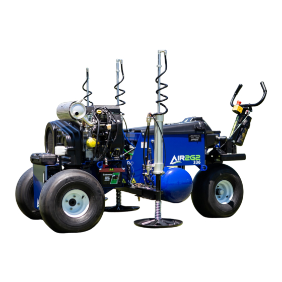
..----87" ( 221 cm)-----. [44.5'' ( 1l 3 =] Air2G2 336 SPECIFICATIONS NOTE: Specification and design are subject to change without notice. Width, pad to pad 87 inches (221 cm) Wheel base 44.5 inches (113 cm) Probe width 72 inches (183 cm) Length 94 inches (238.76 cm) -
Page 19: For Safe Operation
FOR SAFE OPERATION 1) When operating the AIR2G2®-336 safety is of the utmost importance DO NOT MOVE THE MACHINE WHEN THE PROBES ARE IN THE GROUND. DAMAGE WILL OCCUR. 2) Before starting the engine always make a pre-operation inspection to prevent damage to property or personnel. - Page 20 8) Fuel is flammable. DO NOT use cigarettes, matches, or operate the machine near any open flame or extreme heat. 9) Do not operate the machine in any unventilated room. Noxious, exhaust gas is discharged from the engine. Carbon monoxide can cause death when inhaled. Use the machine only outdoors. 10) When operating the machine DO NOT TOUCH HOT PARTS, i.e.
- Page 21 NOTE: For extended storage, treat the fuel with a fuel additive and then let the machine run 3-5 minutes before turning off the engine. 18) If replacement parts are needed, use only designated genuine approved parts. Call your dealer or contact GT AIRINJECT INC. at parts@air2g2.com. See warranty registration.
-
Page 22: Pre-Operation Of The Machine
PRE-OPERATION OF THE MACHINE 1) Before starting the machine, check the levels of gasoline and oils in these areas: Make sure the gasoline tank, which is located under the main cover, is filled to within 2 inches (5.08 cm) from the bottom of the filler neck. Full tank is approximately 5 gallons (18.92 liters). Use unleaded (87 minimum octane), leaded may be used if unleaded not available. - Page 23 Check the compressor oil by loosening the fill cap and you can visually see the oil. Make sure the belts are snug while the motor is OFF. Check the axle oil by checking the marked line in the plastic clear reservoir FULL WHEN COLD (see illustration below) Use only 20W-50 oil. Belt tension should be checked between ½...
- Page 24 WARNING! DO NOT TOUCH OR STAND NEAR THE CYLINDER RODS DURING OPERATION. 4) If the engine has not been started for more than 8 hours: Before turning the key to start, turn key to the on position, allow the electronic fuel pump to fill the fuel filter, now turn to start engine. To set engine Speed/RPM for safely moving machine from location to location, slide throttle control ¼...
- Page 25 WARNING! KEEP HANDS AND FEET AWAY FROM THE PADS. WHEN FINISHED USING THE MACHINE, ALWAYS ATTACH THE CHAINS BACK TO THE PIN ON EITHER SIDE OF THE FRAME (I.E. IN A HOME OR STORED POSTION [UP]). 6) The handle bars always rest in the neutral position. In this position, the brake is automatically set. 7) Standing in the operator’s position, PUSH the handle bars to release the brake and engage a REVERSE motion.
- Page 26 process. This process should only take 4-5 seconds to complete. CAUTION! DO NOT STAND NEAR THESE CYLINDERS DURING OPERATION. NOTE (1): If the pitch or golf course is extremely compacted, the operator may want to move the machine every 2 feet (.6096 m) on the first aeration.
- Page 29 With the PLC in 1=AUTO / 2=MANUAL. • • Press 5 and HOLD for 3 seconds. Screen will read “AIR2G2 REVISION 6.2”. • Press 7 & 9 and HOLD SIMULTANEOUSLY. Screen will read HOURS - # OF HOURS MACHINE HAS OPERATED.
- Page 30 OPERATING PLC TO CHECK MACHINE FUNCTIONS INDEPENDANTLY All settings are pre-set by the manufacturer. NOTE: When toggle switch is first turned on, a blow-out or purge of probes will take place Standing in the operators’ position behind the handle bars, flip the toggle switch on the right side of the PLC to the UP/ON position.
-
Page 31: Standard Operations Procedure For The Aeration Process
REMEMBER, when the handle bars are in the neutral position (center) the parking brake will automatically be set. To transport the Air2G2-336 machine, use a heavy-duty trailer or truck with proper tie downs. Ensure that the trailer or truck has all necessary markings and lighting as required by law... -
Page 32: Maintenance And Storage
MAINTENANCE AND STORAGE NOTE: Be sure the beam and all 3 cylinders are secured in the “Home” / stored (UP) position. a) With the PLC in the AUTO/MANUAL mode Press and release 8 (PURGE) and air will be released through the probes. - Page 33 Disconnect the battery or remove the spark plug wires before making any repairs. Disconnect the negative • terminal first and the positive last. Reconnect the positive first and the negative last. Keep hands and feet away from moving parts. If possible, do not make adjustments with the engine running. •...
-
Page 34: Troubleshooting
TROUBLE SHOOTING Condition: Motor will not start. Check the oil and fuel levels. Make sure the battery is charged. Make sure emergency stop-button Solution: has not been pressed. Condition: No air pressure. Solution: Release valve on the compressor should be closed. Check all drainage ports. Ensure #8 on PLC is not Condition: The machine will not move forward or reverse. - Page 42 Item Purpose Mach AIR SYSTEM AS-14-002 (SN) -- INGERSOL-RAND AIR AIR COMPRESSOR COMPRESSOR 2475 AS-14-004 -- STEEL BRAID HOSE (23") TANK AND AIR INJ. REG. SUPPLY HOSE AS-14-008 -- STELL BRAID HOSE (13") PROBE INJ. REG. SUPPLY HOSE AS-14-009 --3/4" REGULATOR INJECTION REGULATORS AS-14-009-N -- NORGREN REGULATOR PANEL NORGREN REGULATOR PANEL MOUNT NUT...
- Page 43 AS-14-029 -- 3/8" MNPT x 1/2" TUBE CYLINDER TOP QE VALVE FITTINGS STRAIGHT AS-14-030 -- 3/8" MNPT x 1/2" TUBE ELBOW PROBE CYLINDERS AND #10 VALVE AS-14-031 -- 1/2" PTC BULKHEAD UNION FRAME BULKHEAD FITTINGS FITTING AS-14-032 -- PROBE CYLINDER ROD COLLAR PROBE CYLINDER ROD SUPPORT CLAMP AS-14-033 -- 1/2"...
- Page 44 AS-16-007-B -- NORGREN FILTER/SEPARATOR FILTER MOUNT WALL MOUNT BRACKET AS-16-007-E -- NORGREN 3/4" AIR AIR SYSTEMS FILTER/SEPARATOR ELEMENT FILTER/SEPARATOR ELEMENT (5 micron) AS-16-043 -- 1/4" NPT MINI BALL VALVE (AIR AIR TANK MANUAL DRAIN VALVE TANK MANUAL DRAIN) AS-16-046 -- CYLINDER QUICK-DUMP VALVE PROBE CYLINDER QE VALVES AS-16-046RK -- CYLINDER QUICK-DUMP VALVE REPAIR KIT...
- Page 45 ASA-14-011 -- AIR INJECTION REGULATOR AIR INJECTION REGULATOR ASSEMBLY ASSEMBLY ASA-14-013 -- AIR INJECTION VALVE MODULE AIR INJECTION MODULE ASSEMBLY ASSEMBLY ASA-14-016 -- 100 PSI AIR INJECTION GAUGE 100 PSI AIR INJECTION GAUGE ASSEMBLY ASSEMBLY ASA-14-017 -- 200 PSI PROBE INJECTION 200 PSI PROBE INJ.
- Page 46 DS-14-015 -- DRIVE AXLE BRAKE PUCKS DRIVE AXLE BRAKE PADS DS-14-018 -- WHITE STEEL WHEEL MACHINE WHEEL DS-14-019 -- 21x12-8 A/Z TLN 800 SLICK MACHINE TIRES NANCO TIRE DS-14-020 -- TIRE AND RIM ASSEMBLY TIRE AND WHEEL ASSEMBLY DS-14-021 -- WHEEL STUD w/ LUG NUT WHEEL STUD w/ LUG NUT DS-14-022 -- 1/2"-20 WHEEL LUG NUT LUG NUT...
- Page 47 ES-14-002 -- BATTERY HOLD-DOWN BRACKET FIBERGLASS BATTERY HOLD-DOWN BRACKET ES-14-003 -- MAIN WIRING HARNESS MAIN WIRING HARNESS ES-14-004 -- DIN RAIL WIRING HARNESS DIN RAIL WIRING HARNESS ES-14-005 -- STEERING ARM WIRING HARNESS STEERING ARM WIRING HARNESS ES-14-006 -- 240v, 4 AMP MINIATURE CIRCUIT DIN RAIL CIRCUIT BREAKER BREAKER ES-14-008 -- TOGGLE SWITCH BUTTON (RED...
- Page 48 UPRIGHT DROP STAND COMPLETE ASSEMBLY ASSEMBLY FRA-1879 -- DRIVE-END DROP STAND AXLE DROP STAND COMPLETE ASSEMBLY ASSEMBLY 3FRA-2007 – CENTER PRESSURE BEAM AIR2G2 336 COMPLETE CENTER BEAM ASSEMBLY 3FRA-2105 – RIGHT PRESSURE BEAM WING AIR2G2 336 COMPLETE RIGHT PRESSURE BEAM WING ASSEMBLY...
- Page 49 3FRA-2104 – LEFT PRESSURE BEAM WING AIR2G2 336 COMPLETE LEFT PRESSURE BEAM WING ASSEMBLY 3FPCLGO.53.5 – LOCK PIN AIR2G2 336 (.5”x 3.5” PIN) ZINC COATED PRESSURE BEAM LOCK PIN FUEL/OIL SYSTEM 468317 -- FUEL TANK PICK-UP TUBE BUSHING FUEL TANK PICK-UP TUBE GROMMET...
- Page 50 PL-14-002 -- CUP HOLDER CUP HOLDER PL-14-004 -- REGULATOR COVER - LEFT REGULATOR COVER - LEFT PL-14-005 -- REGULATOR COVER - RIGHT REGULATOR COVER - RIGHT PL-14-006H -- PLC DASH w/ HOUR METER PLC DASH w/ HOUR METER CUT-OUT CUT-OUT PL-14-008 -- RUBBER T-HANDLE DRAW LATCH MAIN COVER LATCHES PL-14-009 -- MAIN COVER...
Need help?
Do you have a question about the AIR2G2-336 and is the answer not in the manual?
Questions and answers