Table of Contents
Advertisement
Quick Links
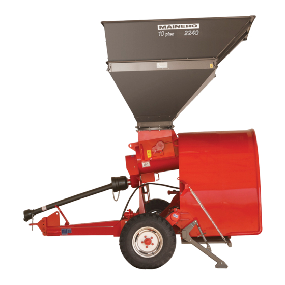
Dry Grain Bagger
model 2240
Operator's safety is one of the main concerns in the objectives of our designs.
The decals referring to safety, protections, covers and other protection characteristics incorporated to the
machine have been included for your safety.
A great percentage of accidents occur by neglect or bad usage.
A good operator uses and maintains the machine adequately, taking the maximum precautions to avoid
accidents.
IMPORTANT: Before trying to operate the machine, read carefully and apply the instructions contend in
this manual.
September, 2010
Series Nº 3
34231-737
1
Advertisement
Table of Contents

Summary of Contents for mainero 2240
- Page 1 Dry Grain Bagger model 2240 Operator’s safety is one of the main concerns in the objectives of our designs. The decals referring to safety, protections, covers and other protection characteristics incorporated to the machine have been included for your safety.
-
Page 2: Table Of Contents
INDEX Warranty Certificate ................................ 3 Technical Start Up Record ............................. 5 Technical Specifications ..............................7 General Dimensions ............................... 8 Objective..................................9 Security Instructions ..............................9-10 Mr. Operator ................................. 10 Safety Stickers................................11 Bagger Identification ..............................12 Tractor ..................................13 Machine - Tractor Coupling ............................14 •... -
Page 3: Warranty Certificate
Product covered by this Warranty is found to be defective in material and/or workmanship (under normal use), MAINERO will, at its sole option, either repair the defective part or replace it with a new genuine part, without charge to the Purchaser for the part or labor. - Page 4 In the event that the Purchaser transfers the property of the Product during the effective warranty period, this Warranty will be transferred to the new owner only if the new owner notify in writing to MAINERO the transfer of ownership and submit the corresponding document as evidence thereof, both to the address mentioned in provision 1 above within fifteen (15) consecutive days from the date of effective ownership transfer.
-
Page 5: Technical Start Up Record
TECHNICAL START UP RECORD Points or items to be seen or discussed, with the owner or operator. Item Instruction given Page Realized Tractor a - Minimum power 60 kW (80 CV) ..........b - PTO shaft. Control R.P.M ............ - Page 6 Item Instruction given Page Realized Filling process stop a - As realize the task ............... Suggestions a - Ground conditions ............... b - Separation between bags ............c - Bag clousure ................d - Bag orientation ................
-
Page 7: Technical Specifications
TECHNICAL SPECIFICATIONS TRACTOR Minimun Power: 60 kW (80 CV ) Power Take-Off (PTO): 540 RPM Hydraulic System: One double acting outlet PTO shaft with protection. START PTO shaft with shear bolt. Safety System: FILLING TUNNEL Ovoid or flattened. Type: Admitted Bag Size: 3.04 m (10 ft) x 60 - 75 m (195 - 245 ft) Bag Mounting: With hoist and basket, retractile support. -
Page 8: General Dimensions
GENERAL DIMENSIONS POSICIÓN DE TRABAJO WORK POSITION TRANSPORT POSITION POSICIÓN DE TRANSPORTE TRANSPORTE DE PUNTA END TRANSPORT WORK POSITION - TRANSPORT POSITION WEIGHT Reference Dimension 2162 4354 3100 1760 3260 3440 1400 kg (mm) END TRANSPORT Reference Dimension 4917 3469 1130 1170 3040... -
Page 9: Objective
OBJECTIVE The Dry Grain MAINERO Baggers, model 2240, are not machines for multiple purposes. They have been designed for a specific and limited use, like is storage in bags of all types of dry, healthy and clean grains. -
Page 10: Mr. Operator
Maintain the hands, feet and clothes away from moving parts. • If you have questions that are not answered in this manual, need additional copies or if the manual was damaged, please contact your MAINERO dealer, or call: MAINERO CUSTOMER SERVICE Tel.: +54+0800-444-0999 E-mail : servicio@mainero.com.ar. -
Page 11: Safety Stickers
SAFETY STICKERS The Safety Stickers are located in the Bagger in the places that are indicated in the Illustration Nº 11 of the Spare Parts Section. The stickers are the following ones and its porpouse is to guarantee your and others security. -
Page 12: Bagger Identification
FIG.2 We suggest to complete the pigeonholes with these data. TRANSPORT Always transport the Bagger 2240, for routes, public roads, etc. has more than enough truck or dray. Fig. 3 Sticking the machine and the hopper to truck floor with at least 4 or 6 ties. These should be the sufficiently strong ones for a sure transfer. -
Page 13: Tractor
SLING She should cut the ties that the Bagger fixes to the means of transport. Use a metallic support with chains or ta- pes like sample the Fig. 4 (not provided), to take the Bagger without hopper. Use half of elevation “F” with a superior capacity to the 2000 kgs. -
Page 14: Machine - Tractor Coupling
MACHINE - TRACTOR COUPLING WORKING POSITION (The machine is end transported) FIG.7 For setting the machine in “Working Posi- tion” i must be accomplishe the indicated steps: 1. Uncouple the machine from the trai- ler vehicle and let it supported on the jack “A”... -
Page 15: Jack
4. Raise jack until free the front tire and withdraw it. The hub “A” Fig. 10 must be rotated in this position half a turn, upwards the chassis. 5. Retire bolt “B” Fig. 11, take the tongue “A” from the handles “C”, take it down and put the bolts with lock in work po- sition. - Page 16 8. Withdraw the back wheel “B” Fig. 13 and the hub “A”, located into the filling tunnel. FIG.13 9. Put the back hub “A” Fig. 13 near to the front hub “B” Fig. 14 with corres- ponding bolts and locks. FIG.14 10.
- Page 17 11. Close the hydraulic cylinder acting from the tractor lever to raise the axle “A” Fig. 16 and install the two wheels “B”. 12. Open the hydraulic cylinder to raise the machine and free the additional support “A” Fig. 17. Close it from the adjuster “B”...
-
Page 18: Hydraulic Hose
TONGUE REGULATION Correct the height of the hitch “A” Fig. 18 at the working tongue, so that the chassis is leveled respect the ground. For this locate the rack to a height H: 25-30 cm Fig. 18 from the floor and the roof of the tunnel parallel to the ground. -
Page 19: Pto Shaft
PTO SHAFT INSTALLATION The PTO Shaft must be installed like is shown in the Fig. 20, one end towards the tractor and the end with shear bolt at the imput shaft of the machine. Prior to mounting we advice: FIG.20 •... - Page 20 WORKING INSTALLATION After executed length corrections, pro- ceed to the definitive working installation: 1. Lubricate the telescopic section “A” Fig 23. 2. Assamble metallic sections and pro- tections. 3. Set the ends of the PTO shft at: a) The imput shaft of the machine, verifying proper installation of the lock “B”...
-
Page 21: Technical Aspects
TECHNICALS FEATURES GRAIN HOPPER The grain hopper inlet is rectangular and is displaced from the base regarding its center Fig. 25. To work, it can be located in two different ways, we recommend locate the longer face, longitudinal or parallel to the ma- chine working direction and the displaced face towards the sel unload wagon. -
Page 22: How To Munt The Bag
HOW TO MUNT THE BA- GGER BAG MOUNTING To install or mount a bag follew the indi- cated steps: FIG.28 1. Free the elastics harness “A” Fig. 28 from the hooks under the lower rack and displace them toward the front side of the tunnel. - Page 23 5. Raise from the winch the parallelo- gram and the basket “A” Fig. 31, up tho the rear line of the tunnel “B” (at the most). FIG.31 6. Place the box “A” with the bag in front of the basket, like shows Fig. 32, with the arrow towards the machine if you have this at the box.
- Page 24 9. With two or more persons, take the bag from the inside of the folds and mount it above the basket, passing it “5 cm” (2 in) towards the tunnel Fig. 34 (as a way that the upper side fits above the hanger and the lower side is supported on the ground).
- Page 25 15. Then take the bag from the lower side of the tunnel (left or right) and insert it over the rack in same proportion (50%), repeat this task in the other side. Then locate the central part of the bag 50% over the central section of the rack.
-
Page 26: Start Bag Filling
21. Mount the rope “A” Fig. 40 over the bag and in front of the folds, and hook it under the rack, passing it by the co- rresponding holes then put the rope “B” (six in total) that are the ones that prevent that the rope “A”, get moved together with the bag, as this goes out. - Page 27 5. Put the brake of the machine in the work place or were it is foresee to start the bag. 6. Start the PTO at 400 RPM approxima- tely. 7. Start the uploading cereal from the self unload wagon, in the grain hopper of the bagger.
-
Page 28: End Of Bag And Closure
BAG END AND CLOUSURE 1. When the end mark of the bag reach the tunnel end, stop loading cereal with the self unload wagon. 2. Empty the bagger grain hopper and the auger. 3. Stop the tractor PTO. 4. Lower the work height H : 10-12 cm (4 - 5 in) Fig. 41 (from rack tho the ground). 5. - Page 29 5. Set the aditional stands “A” Fig. 44 at the chassis sides with the correspon- ding safety lock “B”. Open the adjus- ters “C”, (unscrew) until free the ton- gue in the tractor hinch. 6. Increase the brake circuit pressure, in 30 - 40 kg/cm²...
-
Page 30: Suggestions
SUGGESTIONS GROUND CONDITIONS Is important for a good grain storage and conservation taht the ground for bag filling is to prepared in anti- cipation, with the following characteristics: • Be a high place (not floodable), away from trees. • Hard, not to mark footprints from the tractor and bagger. •... -
Page 31: Bag Clousure
BAG CLOUSURE The bag clousure for “Start” can be done in the following ways: 1. Use 1” x 4” of 2.5 or 3 m (8 or 10 ft) long wood tables, with an inner slot like shows Fig. 47, fold the endsfrom outsi- de to the center and down, being left on the ground a bag width smaller than the table slot. -
Page 32: Plastic Stretching
4. Close for Temperature. Take the extre- me of the bag outside of the tunnel, stretch completely the whole width, join the points superior and inferior and carry out the closing with tempe- rature in the whole width from the bag some 100 mm of the extreme. -
Page 33: Bag Orientation
BAG ORIENTATION The bag orientation must be always in North - South direction, procure an equal isolation in both sides. Our country is in a very austral position of the southern hemisphere, for that reason, the sun describes its way from East to West always by the North quadrant. - Page 34 Also, when this grains with high humidity levels are exposed again to the air (oxygen) at the extraction mo- ment, it is produced a fast aerobic microorganism multiplication that quickly degrade the material. Hence, it must be dried immediatly after being extracted and before being commercialized. BAG DURABILITY The maximum allowed storage time is a very important data and must be checked out with the bag supplier.
- Page 35 • If eventualli the gauge DO NOT INDICATE PRESSURE, it can be damaged or the circuit and deposit liquid is in bad condition. Ask the technical service of your MAINERO dealer. • Only use MAXIMUM PRESSURE in special cases. Do not use, for normal working use because it will cause futible over efforts, premature damages in the machine and possible breaking of the bag.
-
Page 36: Transport Position
TRANSPORT POSITION The machine can be transported inside the field or agricultural exploitation, by two different ways: A) Working position transport. B) End transport. A) WORKING POSITION TRANS- FIG.54 PORT To transport in this position the machine must be raised totally, close the valve “A” Fig. - Page 37 4. Put the jack “A” Fig. 57 at the chassis left side and start to lift, until liberaste the tongue “B” and uncouple from trac- tor. FIG.57 5. Lower the jack, put the rear axle end “A” Fig. 58 (inside the tunnel) and the wheel “B”...
- Page 38 7. Raise the working tongue “A” Fig. 60, from the handles “C”, attach with the bolt “B” and the lock. Execute this raising task between al least two people. FIG.60 8. Place the transport tongue “A” Fig. 61 in the chassis left side with the bolt “B” and the lock.
- Page 39 9. Position the light kit “A” like shows the Fig. 63, and carry out the electric con- nection to the tractor unit before trans- port the machine. Check its correct operation. FIG.63 ACCESSORIES BOX In each machine a metallic box is included with tools whose content, use and number of pieces are detail next: Nº...
-
Page 40: General Considerations
GENERAL CONSIDERATIONS • Allow to operate the machine only people with knowledge on its functions, controls, safety standards, etc. • Verify the tractor extinguisher installatioin and condition (read and understand its usage instructions). • Read all the safety, maintenance, etc, instructions indicated on the machine. •... -
Page 41: Lubrication
LUBRICATION For the initial start up is convenient that the operator accomplish a check and a general lubrication as a way to get familliarized with the location of the greasing points. • Clean the grase nipples anad the grease pump every time you proceed to lubricate. •... -
Page 42: Mr. Operator "What You Must Not Do
Mr. Operator: “WHAT YOU MUST NOT DO” • Work with the tractor out of standard regarding its draw bar, PTO, etc. • Work with a PTO reime higher to 540 RPM. • Forget to do the correct maintenance, lubrication, etc, plan. •... -
Page 43: Indications To The User Of Agricultural Machines
INDICATIONS TO THE USER OF AGRICULTURAL MACHINERY SAFETY It is crucial for avoiding accidents to know very well the use of the agricultural machinery, being this indispensable to avoid accidents to those who operate or to third parties.. We suggest follow these general indications: 1. - Page 44 The safety is an obligation of high responsibility and conscience. This obligation is directly linked to the operator protection. Is necessary to self examine to determine if one knows all the actions to have present to avoid accidents. MAINERO SAFETY DEPARTMENT...
-
Page 45: Spare Parts
SPARE PARTS... - Page 46 Self lock hex nut RM 18 mm 27963-111 Hex bolt RM 8 x 30 mm 21705-343 PTO shaft support 43940-215 Nonskid Tape (L: 350 mm) 43900-933 Nonskid Tape (L: 100 mm) 43900-935 Hex nut RM 12 mm 27963-108 Plain washer Ø 1/2” 20801-106 2240...
-
Page 47: Ilustration N° 1: Chassis
ILLUSTRATION Nº 1: CHASSIS... - Page 48 Hex bolt RM 16 x 40 mm 21705-480 Straight grease nipple 1/8” 24902-101 Self lock nut RM 16 mm 27963-110 Support left exterior axis of wheels 43925-207 Hex bolt RM RM 10 x 110 mm 21705-389 Hex bolt RM RM 10 x 30 mm 21705-374 2240...
-
Page 49: Ilustration N° 2: Tunnel
ILLUSTRATION Nº 2: TUNNEL... - Page 50 Wheel axle 43925-212 Plastic precinct 32102-250 Hose Ø ¼” x 4160 mm 43963-122 Male-male adapter ½” UNF JIC 37º - ½” BSPT 21110-104 Male fast coupler ½” NPT 20204-102 Female plastic plug 20212-102 Seal kit for hydraulic cylinder 30664-485 2240...
-
Page 51: Ilustration Nº 3: Wheel Axle
14 15 ILLUSTRATION Nº 3 : WHEEL AXLE... - Page 52 Grease nipple 90º 24905-100 Hex bolt RM 10 x 45 mm 21705-377 Spacer for axle auger 43941-602 Auger 43941-212 RH SN bolt RM 10 x 30 mm 21409-329 Auger tube 43941-211 Hex bolt RM 12 x 30 mm 21705-407 2240...
-
Page 53: Ilustration N° 4: Pto Shaft - Auger
ILLUSTRATION Nº 4: PTO SHAFT AND AUGER... - Page 54 Plain washer galv. Ø 3/8” 20801-104 Plain washer galv. Ø 1/4” 20801-102 Hex bolt RM 8 x 20 mm 21705-339 Hex bolt RM 10 x 30 mm 21705-374 Turning ring 43974-215 Lock turning ring 43974-610 Long upper extension 43974-214 Short upper extension 43974-612 2240...
-
Page 55: Ilustration N° 5: Bolted Hopper
ILLUSTRATION Nº 5: BOLTED HOPPER... - Page 56 Hex bolt ½” x 4 ½” 21402-241 Winch box 41147-210 Spacer 41147-614 Handle 41147-212 Hex bolt 3/8” x 1 ¼” 21402-183 Self lock hex nut RM 10 mm 27963-107 Drive sprocket 41147-610 Lock bushing 41147-611 Lock 41147-612 Plain washer Ø 3/8” 20800-104 2240...
-
Page 57: Ilustration N° 6: Lower Tray And Hanger
15 16 ILLUSTRATION Nº 6 : LOWER TRAY AND HANGER... - Page 58 Valve Mod. VCA- A - B 3/8” BSP 37213-920 Tee male-female for circuit hydraulic 301-6-6-6 26521-102 Elbow 45º male - female 22552-103 Glycerin gauge 34205-121 Male-male adapter 21110-103 Helical protector 41563-614 Hydraulic hose Ø ¼” x 455 mm 43963-125 Seal kit for caliper of brake 35458-105 2240...
-
Page 59: Ilustration N° 7: Brake Circuit
ILLUSTRATION Nº 7: BRAKE CIRCUIT... - Page 60 Cotter pin DIN 94 Ø 3 x 40 mm 25102-170 Axle 43925-200 Transport tongue double 43940-216 Transport tongue simple 43940-211 Short neck bearing gear 16 T. 23804-102 Long neck bearing gear 16 T. 23804-101 Axle point complete mount 43925-011 2240...
-
Page 61: Ilustration N° 8: End Transport Kit
ILLUSTRATION Nº 8 : END TRANSPORT KIT... - Page 62 Self lock hex nut RM 16 mm 27963-110 RH lights support 43964-202 Washer 45281-978 Spring 36018-936 Bolt type tank 3/16” 21411-102 Pressure washer Ø 3/16” 20810-105 Hex nut 3/16” 27903-102 Self-adhesive platelet 38 x 38 mm for seal 35452-101 2240...
-
Page 63: Ilustration N° 9: Lights Circuit
ILLUSTRATION Nº 9 : LIGHTS CIRCUIT... - Page 64 Snap ring DIN-472 72 x 2,5 mm 20601-157 Radial ball bearing 62-2RS – 6207-2RS 60406-207 Axle sleeve 48776-610 Hex bolt RM 12 x 35 mm 21705-408 Drive axle 48776-611 Key DIN 6885 10 x 8 x 40 mm 23325-317 2240...
-
Page 65: Ilustration N° 10: Gear Box
ILLUSTRATION Nº 10: GEAR BOX... - Page 66 SPARE PARTS LISTING OF THE ILLUSTRATION Nº 11 POS. DENOMINATION SPARE Nº POS. DENOMINATION SPARE Nº “MAINERO” sticker – Long. 580 mm 30642-259 “2240” model sticker 30642-702 “Do not remove protection” sticker 30642-467 “Maximum Speed– 30 Km/h” sticker 30642-448 “Stop the Engine” sticker 30642-228 “MADE IN ARGENTINA”...
-
Page 67: Ilustration N° 11: Stickers
MADE IN ARGENTINA 2240 MAXIMUM SPEED 30 0 km/h 30642-248 30642-228 8 DANGER TILTING AND WORKING Stop engine before unclog or make HEIGHT any adjustment. TILTING O F 30642-443 TUNEL Bes t Mínimum 60mm WORKIN G HEIGHT 250 - 300 mm READ OPERATOR´S MANUAL... - Page 68 VALUES OF IT PRESSES OF THE METRIC SCREWS 10.9 12.9 Grade and 10.9 12.9 12.9 marks in heads 12.9 10.9 12.9 Grade and marks in nuts class 4.8 class 8.8 o 9.8 class 10.9 class 12.9 greased greased greased greased Diameter Lb-ft Lb-ft...
-
Page 69: Metric And No Metric Bolts Tighten
VALUES OF IT PRESSES OF THE NOT METRIC SCREWS 1 o 2 Grade SAE and WITHOUT MARKS marks in heads Grade SAE and WITHOUT MARKS marks in nuts class 1 class 2 class 5 , 5.1 o 5.2 class 8 o 8.2 greased greased greased... - Page 70 MANUAL SIGNS FOR THE AGRICULTURAL INDUSTRY 1 Purpose and range 1.1 These graphics show manual signs for work in the agricultural industry. Especially if there is too much noise or the distance too big that verbal communication is impossible. 1.2 The purpose of the manual signs is too have a simple system of communication. Particularly orientated to the security of the users of the agricultural and forestal machines.
-
Page 71: Signal For Agricultural Use
Fig. 7 – SLOW DOWN – Hold up your Fig. 8 - START THE ENGINE – Circulate Fig. 9 – STOP THE MOTOR – Move arm the horizontally to one side. The inte- your right hand with the interior side to the arm in height of your belt. - Page 72 NUMERIC INDEX Number Ilust. Pos. Number Ilust. Pos. Number Ilust. Pos. Number Ilust. Pos. 20204-102 30642-315 20212-102 21705-377 27963-106 30642-367 20601-143 21705-389 30642-443 20601-157 21705-407 30642-448 20800-102 30642-451 20800-104 21705-408 30642-467 20801-102 27963-107 30642-487 20801-103 30642-512 21705-413 30642-513 21705-414 30642-515 21705-480 30642-556 20801-104...
-
Page 73: Numerical Index
NUMERIC INDEX Number Ilust. Pos. Number Ilust. Pos. Number Ilust. Pos. Number Ilust. Pos. 43900-223 43940-214 47538-274 43900-224 43940-215 48776-610 43900-225 43940-216 48776-611 43900-226 43940-219 60406-205 43900-228 43940-220 60406-207 43900-230 43940-221 65230-206 43900-231 43940-222 43900-235 43940-600 65230-209 43900-238 43940-601 43900-240 43941-204 65900-211 43900-241... -
Page 74: Instructions For Spare Parts Request
INSTRUCTIONS ON HOW TO ORDER SPARE PARTS To make delivery easier and to avoid confusions or delays, we recommend to order as follows: a - Parts quantity. b - Part type or name. c - Part number. d - Machine serial number. e - Machine number. - Page 75 ANNOTATIONS:...
- Page 76 ANNOTATIONS:...
- Page 77 ANNOTATIONS:...
- Page 78 ANNOTATIONS:...
- Page 79 ANNOTATIONS:...
- Page 80 ANNOTATIONS:...
Need help?
Do you have a question about the 2240 and is the answer not in the manual?
Questions and answers