Table of Contents
Advertisement
Quick Links
Advertisement
Table of Contents

Subscribe to Our Youtube Channel
Related Manuals for RIX Industries 2V3B-4.1V

Summary of Contents for RIX Industries 2V3B-4.1V
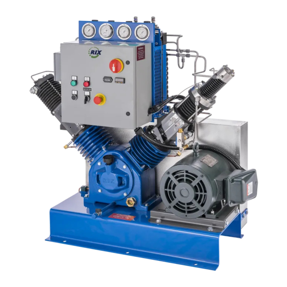
- Page 1 OPERATING INSTRUCTIONS and PARTS LIST for RIX INDUSTRIES DRY OXYGEN COMPRESSOR MODEL 2V3B-4.1V 40 PSIG Inlet, 2500 PSIG Discharge S/N’s 12991 and Above P/N: MAN-2V3B-4.1V, Rev. (F) 4900 Industrial Way Benicia, CA 94510 Phone 707-747-5900 Fax 707-747-9200 Parts Fax 707-758-0398...
- Page 2 MAN-2V3B-4.1V REVISION PAGE Pages Revised Revision Date Brief Description 10/01/08 3-4, 7-1, 7-3, REVISED BOM TO AS-BUILT; UPDATED 7-5, 7-6, 7-14 DRAWINGS TO REFLECT BOM CHANGE 9/18/09 ADDED DRAWING A11151 PG. 2 CHANGED “SHOULD” TO “MUST” FOR COMPRESSOR MOUNTING PG. 4 ADDED REFERNCE TO CHECKING THAT OIL WAS ¾...
- Page 3 MAN-2V3B-4.1V Pages Revised Revision Date Brief Description D (con’t) Changed oil change interval to include annually. Added d. regarding retensioning of belts. Removed note about third stage valve stop. Removed reference to 2 ¼ air cooled cylinder. Added illustrations showing proper dipper orientation.
- Page 4 MAN-2V3B-4.1V Pages Revised Revision Date Brief Description Added part #’s for –P1A & -P1B sheave and E (cont’) belts. Deleted 263 & 268. Now part of electrical panel. New Bom for Electrical Panel B10979 Replaced with B12726 B12570 New Elec Wiring Diagram...
-
Page 5: Table Of Contents
TABLE OF CONTENTS 2V3B-4.1V Title Page Table of Contents ....................i Drawing Index ....................iii REGISTRATION PAGE (Compressor Data / Performance Summary) ... iv Oxygen Cleaning Requirements ................. v Safety Precautions ....................vi Compressor Warranty ..................vii 1. COMPRESSOR OVERVIEW DESCRIPTION... -
Page 6: Table Of Contents
TABLE OF CONTENTS 2V3B-4.1V 6. TROUBLESHOOTING…………………………………………………………………12 CORRECTIVE MAINTENANCE –MECHANICAL SYSTEMS ALIGNMENT OF DRIVE PULLEYS ............13 TIGHTENING DRIVE BELTS ..............13 SECTION II – REPAIR CYLINDER HEADS ..................14 COMPRESSOR VALVES ................15 7.4.1 1ST STAGE VALVE ..................16 7.4.2 2ND STAGE VALVE .................. -
Page 7: Drawing Index
DRAWING INDEX MODELS 2V3B-4.1V Mechanical Drawing No. Stage Valve Assy ........................ A11192 Stage Valve Assy ....................... A11193 Stage Valve Assy ........................ A11195 Stage Piston Assy ....................... A11194 Instructions for Installing Spiral Piston Rings on Floating or Removable Pistons ....A3534 Oil Wiper Assembly ........................ -
Page 8: Registration Page (Compressor Data / Performance Summary)
REGISTRATION PAGE RIX MODELS 2V3B-4.1V Serial Numbers 12991 and above Compressor Design: Three stage, oil-free compression, air-cooled Cylinder Sizes: 2.25” & 1 3/8” & 5/8” x 3” stroke Gas to be compressed: Clean dry Oxygen Operating Pressures: 30-40 psig inlet, 2500 psig discharge, 100°Fmax. Ambient temp Flow Rate: 10 SCFM (600 SCFH) with 40 PSIG @ 100°F suction... - Page 9 OXYGEN COMPATIBILITY REQUIREMENTS FOR ALL RIX O2 COMPRESSORS To prevent FIRE, SERIOUS INJURY or DEATH, it is the User’s responsibility to ensure that all parts used in the oxygen contacting areas of the compressor are cleaned for oxygen service prior to installation. All gas piping and storage systems connected to the compressor must be oxygen clean and constructed of oxygen compatible materials.
-
Page 10: Safety Precautions
SAFETY PRECAUTIONS Safety precautions are necessary for the protection of personnel and equipment. Prior to any attempt to install, operate, maintain, troubleshoot or repair any part of the compressor, all warnings and cautions included here and/or appearing throughout this manual should be thoroughly reviewed and understood. -
Page 11: Compressor Warranty
RIX INDUSTRIES' COMPRESSOR WARRANTY RIX Industries warrants all 2V3B compressors as follows: Twelve (12) months of operation or eighteen (18) months from date of shipment or 2,000 hours of operation, whichever occurs first, covering materials and workmanship. Warranty does not cover normal wear or consequential damages. -
Page 12: Compressor Overview
CHAPTER 1 - COMPRESSOR OVERVIEW This manual is intended to provide information pertinent to the installation, operation and maintenance of the RIX Model 2V3B-4.1V Oxygen Compressor. See serial numbers on the registration page of this manual for applicability. DESCRIPTION This is a 3 stage, 3 cylinder, air-cooled, oil-free compressor. The unit has been mechanically designed for the compression of dry oxygen to the pressures indicated on the registration page of this manual. -
Page 13: Installation
1 3/4 Quarts (1.66 liters) VISCOSITY: Above 60˚F. - SAE 30W Between 32˚ and 60˚F - SAE 20W Between 20˚ and 32˚F - SAE 10W - synthetic oil preferred Below 20˚F - SAE 5W - synthetic oil required MAN-2V3B-4.1V REV (E) -
Page 14: Electrical Connections
After an extended storage (or if stored without climate control) the crankcase cover plate should be removed and the roller bearings inspected for possible corrosion. Apply oil to all bearings before replacing cover. Also, lift up oil packing boxes (inside distance pieces) and lubricate guide cylinders. MAN-2V3B-4.1V REV (B) -
Page 15: System Checkout
"on" pressure setting (automatic mode only). Test temperature shutdown switch by manually lowering setting while operating at full pressure. SEE CHAPTER 4 FOR CONTROL SYSTEM INFORMATION M M AN-2V3B-4.1V REV (C) -
Page 16: Normal Operating Pressure Ranges
Chapter 6, Troubleshooting, for corrective action. RELIEF VALVE SETTINGS: Stage Symbol Set Point Suction 50 Psig 1st Stage 300 Psig 2nd Stage 1000 Psig 3rd Stage 2800 Psig M M AN-2V3B-4.1V REV (C) -
Page 17: Control System
HOA Switch in HAND or OFF mode prior to pulling the E-Stop button. An HOA (HAND/OFF/AUTO) switch is provided on the control panel which allows operator choice of modes. Details of the two operating modes are as follows: Manual Mode of Operation MAN-2V3B-4.1V REV (E) - Page 18 "cut in" setting. The compressor will continue cycling until the selector switch is moved to either HAND or OFF. f. The unit may be stopped at any time by switching the HOA to OFF. MAN-2V3B-4.1V REV (F)
-
Page 19: Routine Inspection And Scheduled Maintenance
Refer to the parts lists in the RIX manual when ordering all parts. Use only oxygen compatible O-ring grease and either Viton or Teflon O-rings in gas piping areas. MAN-2V3B-4.1V REV (D) -
Page 20: Scheduled Maintenance
The pressure relief valves should be removed from the compressor, inspected for cleanliness, and tested for correct set-point every 8000 hours or once per year. If a valve fails to lift at its rated pressure, it must be readjusted, and if necessary, rebuilt or replaced. MAN-2V3B-4.1V REV (E) -
Page 21: Gas Piping Leak Check
The customer should establish reference data for use in scheduled maintenance by taking gauge readings when the compressor is running under normal operating conditions. The perimeter of valve seats and o-rings should be lightly lubed with oxygen compatible grease to ease assembly. (see additional information in chapter 7) MAN-2V3B-4.1V REV (E) -
Page 22: Piston Rings
PISTON ROD OIL SEALS: The oil seals prevent crankcase oil from leaking into the distance piece area. If leakage occurs, remove and clean piston rod and replace seals. If scratches are found on rod surface, refinish per instructions in chapter 7. MAN-2V3B-4.1V REV (E) -
Page 23: Troubleshooting
Leak in downstream (customer) piping Shutdown due to high discharge temperature: a. Low interstage pressure (see above causes) b. Inoperative cooling fan (or reverse rotation) c. Inadequate ventilation around compressor or blocked cooling fins M M AN-2V3B-4.1V REV (C) -
Page 24: Corrective Maintenance -Mechanical Systems
Move the motor outward until the desired belt tension is achieved. Correct belt tension allows one quarter inch deflection with 8-10 lb. force applied per belt at mid-span. Tighten motor tie-down bolts and replace belt guard. Inspect and retighten new belts as required after 24-48 hours of operation. MAN-2V3B-4.1V REV (D) -
Page 25: Section Ii - Repair
Relieve pressure and allow heads to cool. Disconnect piping from the head. Note the orientation of the head on the cylinder to ensure proper reassembly. Remove the retaining nuts using an alternating pattern; carefully lift the head from the cylinder. Discard the used O-rings. MAN-2V3B-4.1V REV (B) -
Page 26: Compressor Valves
RIX #45-1007 (Krytox O2 and breathing compatible). Avoid tilting the valve seat when installing into the head and apply even pressure around the circumference until the valve is completely installed. Note: See Drawing A5089G for O-ring installation and material information. MAN-2V3B-4.1V REV (D) -
Page 27: 1St Stage Valve
Carefully install the head assembly, making sure the suction reed valve does not fall out of place. Note: it may be easier to mount the head on the cylinder off the compressor and then install the two together. Install nuts and tighten sequentially in 5 ft-lb. increments to 30 ft-lbs. MAN-2V3B-4.1V REV (D) -
Page 28: 2Nd Stage Valve
Install head on valve assembly with 1.025" diameter counterbore for discharge port towards the flywheel side of pump. Bolt down assembly with nuts and flat washers and torque to 30 ft-lbs. MAN-2V3B-4.1V REV (B) -
Page 29: 3Rd Stage Valve
Reinstall the head and tighten in 5 ft-lb. increments to 15 ft-lbs (lubed threads). CAUTION The nuts holding the head in place must be removed and installed using an alternating pattern. Verify the head is on square and not cocked. Overtightening may damage the valves and/or head. MAN-2V3B-4.1V REV (B) -
Page 30: Cylinders
Reinstall the head per the applicable valve assembly instructions. Note: make sure valve cutout in top of cylinder (if any) is oriented to coincide with suction valve in head. Rotate the flywheel by hand several times to be certain that the parts are free. MAN-2V3B-4.1V REV (B) -
Page 31: Replace Piston Rings, 2Nd Stage
Repeat operation for the remaining rings. Reinstall the head per the valve assembly instructions, Section 7.4.2 Rotate the flywheel by hand several times to be certain that the parts are free. Piston ring break-in: None required. MAN-2V3B-4.1V REV (B) -
Page 32: Replace Piston Rings, 3Rd Stage
Install piston in sleeve tool and insert piston back into cylinder with stubbed end up toward head. Reinstall the cylinder and head in accordance with instructions. Rotate the flywheel by hand several times to be certain that the parts are free. Piston ring break-in: None required. MAN-2V3B-4.1V REV (B) -
Page 33: Piston Rods & Oil Wiper Seals
Screw the rod into the guide piston until the threads bottom. Reinstall the cylinder assemblies and adjust piston rod per instructions below. CAUTION The piston to cylinder head clearance adjustment is critical. Insufficient clearance will result in the piston hitting the head. MAN-2V3B-4.1V REV (B) -
Page 34: Piston Rod Adjustment
Tighten locking screw hand tight with 7/64" allen wrench (Note: overtightening may dislodge packing box) and then secure using the jam nut. Turn the flywheel by hand a few revolutions to be certain that everything is clear before starting the compressor. Oil Packing Break-In: None required. MAN-2V3B-4.1V REV (B) -
Page 35: Crankshaft Shaft Seal
Remove nuts holding down the guide cylinder and carefully lift the guide cylinder off of the guide piston. Reinstall in reverse order. Install with mark “F” or "M" (on lower flange of cylinder) towards flywheel. Use new gaskets if necessary. MAN-2V3B-4.1V REV (B) -
Page 36: Connecting Rods
Note: See instructions in next paragraph for correct oil dipper location. Install lockwashers and nuts and tighten the nuts to 15 ft-lbs torque. WARNING: Incorrect installation of oil dippers can lead to insufficient lubrication and catastrophic failure. Incorrect Orientation Correct Orientation MAN-2V3B-4.1V REV (E) -
Page 37: Main Bearings
Connect all other equipment in reverse order of disassembly. Turn the flywheel by hand a few revolutions to be certain everything is clear before starting the compressor. Start the compressor and check for gas or oil leaks. If leakage is present, repair as required. MAN-2V3B-4.1V REV (E) -
Page 38: Clearances & Tolerances
.625 - .626 .001 in. diametrical wear Valve Reeds: Replace at the presence of any visible ridge or other damage Valve Seats: Replace if worn or pitted enough to cause insufficient seating. Seals: Visual Any leakage should be corrected MAN-2V3B-4.1V REV (B) -
Page 39: Wrench Torque's
Oil Wiper Box Set Screw............. 1-2 Piston Rod Jam Nuts..............25 Distance Piece Mounting Bolts............30 Guide Cylinder Nuts ..............30 Connecting Rod Nuts..............15 Crankcase End Cover Bolts ............30 Flywheel Bushing Bolts..............40 Motor Sheave Hub Bolts..............25 _________________________ Over-tightening will damage valves and/or head MAN-2V3B-4.1V REV (B) -
Page 40: Compressor Parts List
COMPRESSOR PARTS LIST MODEL 2V3B-4.1 & 2V3B-4.1V REF. DWG. NO. B10961 PER PER REF PART DESCRIPTION ASSY UNIT * NO NO. IMPORTANT Any parts that come in contact with Oxygen MUST be Oxygen Cleaned An "X" at the beginning of a part number signifies oxygen clean. Parts with this designation are specially cleaned and supplied in sealed plastic bags. - Page 41 COMPRESSOR PARTS LIST MODEL 2V3B-4.1 & 2V3B-4.1V REF. DWG. NO. B10961 PER PER REF PART DESCRIPTION ASSY UNIT * NO NO. XA15-A7799 Valve Assembly, 2nd Stage (incls. 1-8)(Ref. Dwg. A7799) X123-044-5 1. O-ring X123-045-5 2. O-ring X123-035-5 3. O-ring X123-025-5 4.
- Page 42 COMPRESSOR PARTS LIST MODEL 2V3B-4.1 & 2V3B-4.1V REF. DWG. NO. B10961 PER PER REF PART DESCRIPTION ASSY UNIT * NO NO. X1-D2602 Cylinder Assembly, 1st Stage X123-152-5 O-ring, 1st Stage Cylinder to Head XAO15-A7458 Valve Assembly, 1st Stage (incls. 1-8)(Ref. Dwg. A7458) X17-410 1.
-
Page 43: Crankcase Parts List
Wrist Pin, 1" 34-677 Bolt, Socket Head Cap Screw, 1/4-20, 1" L, GR8, HT alloy steel 8-C3015 Guide Piston, 1" pin bore 91-A4992-1 Key, square 32-4149 Bolt, hex head 3/8-16 x 3", grd 5 *Recommended Spares P/N: MAN-2V3B-4.1V REV (A) -
Page 44: Accessory Parts List
Repair Kit - BPR 42-116 Cooling Fan/Motor 50/60 Hz A156-D3632 Beltguard Assembly A70-D3634 Bedplate Assembly HX1,2,3 X71-6949 Heat Exchanger X10-C2580 PG/RV Manifold A148-C2568 Shroud Assembly 40-D2713 Bracket, Fan Mounting 40-B6240-1 Bracket, BPR 40-A8045 Lifting Bracket *Recommended Spares P/N MAN-2V3B-4.1V rev (C) -
Page 45: Plumbing Parts List
V-Belt, -P1C and -P1D 41-B75-1 V-Belt, -P1A and -P1B 62-A7507-1 Label, Oxygen Service 62-A7514 Label, Factory Authorized Parts 62-A7353 Label, Check Oil 62-416 Label, Control Devices 62-422 Label, Automatic Equipment 20-4745 Washer, Star #10 62-A8471 Label, Rotation *Recommended Spares P/N MAN-2V3B-4.1V rev (E) - Page 46 Tube SS, 3rd Stage Discharge to Hx 28 X54P-64HBUSS Union 29 X455-B6249 Tube SS, 3rd Stage, Hx to Rv 30 X455-C2575 Tube SS 31 X54P-1/4HHPSS Pipe Plug 32 X54P-6GBUSS Connector, Female 33 X54P-1/4CRSS Pipe Elbow, Male 34 54-4746 Pipe Nipple *Recommended Spares P/N MAN-2V3B-4.1V rev (A)
- Page 47 Tee, Union 37 455-C2574-2 Tube Br 38 455-C2574 Tube Br 39 455-C2574-1 Tube Br 40 X123-904-3 O-Ring 42 X54P-41/4F50GSS Adapter, St Female Pipe 43 X54P-1/41/8PTRB Pipe Thread Reducer 44 X54P-1/4MROSS Pipe Tee, Male Run *Recommended Spares P/N MAN-2V3B-4.1V rev (A)
-
Page 48: Electrical Parts List
26 E-STOP 76-12606 Emergency Stop Switch 138-12615 Terminal Block Jumper 62-12622 Emergency Stop Legend Plate 62-12621 Run Legend Plate 62-12625 Stop Legend Plate 163-12598 Fuse, 6.25 Amps 163-12595 Fuse Holder 138-12616 Terminal Block Jumper *Recommended Spares P/N MAN-2V3B-4.1V REV (E) - Page 49 DESCRIPTION DATE APPROVED data contained herein are the confidential and proprietary property of RIX Industries and may not be used, copied, reproduced, or disclosed for any purpose, without the written permission of RIX Industries. NOTES: 1. APPLY A VERY SMALL AMOUNT OF LOCTITE 290 (GREEN) TO ITEMS 4.
- Page 50 X32-1184 SCREW, FLAT HD X32-4171 SCREW, RND. HD. X15-C2445 VALVE PLATE X15-A7792 REED VALVE X123-025-5 O RING VITON X123-035-5 O RING VITON X123-045-5 O RING VITON X123-044-5 O RING VITON ITEM QTY. DESCRIPTION MATERIAL...
- Page 51 Welds 1/32 and data contained herein are the DRAWN ON SAN FRANCISCO BAY SINCE 1878 Cham. 11/2/2009 confidential and proprietary Angles property of RIX Industries and .XXX .005 TITLE CHECKED VALVE ASSEMBLY may not be used, copied, Cast .XXXX .001...
- Page 52 This drawing and the information and DESCRIPTION DATE APPROVED data contained herein are the confidential and proprietary property of RIX Industries and may not be used, copied, reproduced, or disclosed for any purpose, without the written TOP OF PISTON permission of RIX Industries. NOTE:...
- Page 53 INSTRUCTIONS FOR INSTALLING SPIRAL PISTON RINGS ON FLOATING OR REMOVABLE PISTONS Refer to applicable piston assembly drawing in manual Some compression stages use spiral wound compression rings. The pistons maybe be fixed to the rod and removable, or floating. To replace the piston rings, remove the head per service manual instructions. With the flywheel rotated to bring the piston to top dead center, unbolt and lift the cylinder up and over the piston, or, if directed, pull the piston out of the cylinder.
- Page 63 32-4149 (REF) BOLT, HEX HEAD 3/8-16 x 3" L, GD 5 ZINC DETAIL C CAD DRAWING - DO NOT CHANGE MANUALLY (Unless Otherwise CONTRACT NO. RIX INDUSTRIES Proprietary Drawing Tolerances Noted) AIR AND GAS COMPRESSOR MANUFACTURERS ` 1/16 This drawing and the information and...
- Page 64 BOLT, SOCKET HEAD, 1/4-20, 1/2 L, GR. 8, B. OX. 20-1017 WASHER, LOCKING, 1/4 CAD DRAWING - DO NOT CHANGE MANUALLY 32-A8560 BOLT, CONNECTING ROD (Unless Otherwise CONTRACT NO. RIX INDUSTRIES Proprietary Drawing Tolerances Noted) 7-C3016 CONNECTING ROD AIR AND GAS COMPRESSOR MANUFACTURERS ` 1/16...
- Page 65 PART NO. DESCRIPTION QTY. 976‐108 CAPACITOR, FAN/MOTOR 76‐10404 COIL/CONTACT (STARTER) 42‐116 FAN/MOTOR 163-12597 FUSE 3.5 AMPS. 163-12598 FUSE 6.25 AMPS. 113‐10156 HOURMETER SELECTOR SWITCH (HAND‐OFF‐AUTO) 76-12604 76-12627 LED INDICATING LIGHT, GREEN (RUNNING) 76-12628 LED INDICATING LIGHT, RED (SHUTDOWN) 107‐7072 ELECTRIC MOTOR 76‐10405 OVERLOAD X76-714-2500 PRESS. SWITCH, DISCH. SET @ 2500 PSI X76-713-40 PRESS. SWITCH, INLET SET @ 30 PSI OFF, 40 PSI ON 76-12592 RELAY 138‐5531...
- Page 69 INPUT PRIMARY TRANSFORMER SECONDARY TRANSFORMER INPUT VOLTAGE OVERLOAD 2V3 MODEL VOLTAGE SETTING SETTING RANGE SETTING 230VAC/60HZ H3‐H4 PRIMARY X1-X2 SECONDARY 220/230/240 24 AMPS 460VAC/60HZ H1‐H4 PRIMARY 440/460/480 12 AMPS X1-X2 SECONDARY 380VAC/50HZ H2‐H4 PRIMARY X1-X2 SECONDARY 380/400/415 15 AMPS 230VAC/50HZ H3‐H4 PRIMARY X1-X2 SECONDARY 220/230/240 24 AMPS P1A‐6.2 230VAC/60HZ H3‐H4 PRIMARY...
- Page 70 P/N 515-910 ,X515-910 P/N 515-911 ,X515-911 P/N 515-792 ,X515-792 P/N 515-829 ,X515-829...
- Page 73 P/N: 76-713, X76-713...
Need help?
Do you have a question about the 2V3B-4.1V and is the answer not in the manual?
Questions and answers