
Summary of Contents for NEURON THC
- Page 1 NEURON C N C E L E C T R O N I C S INDUSTRIAL TORCH HEIGHT CONTROL USER MANUAL NEURON CNC ELECTRONICS 08.01.2020...
-
Page 2: System Description
The THC module functions based on the principle that the amount of voltage in the plasma arc between the torch and the material is directly proportional to the length of the plasma arc. In other words, if the torch is closer to the plate the arc voltage will be less than if the torch is further away from the plate assuming all other cutting parameters are equal. -
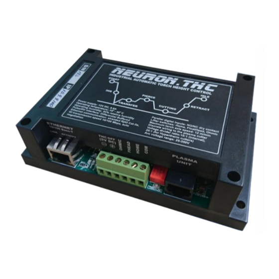
Page 3: Specifications
Neuron.THC. Operator Control Module The Operator Control Module includes screw terminals for connection “Cutting Run/Stop” switch, “Torch Up”, “Torch Down” buttons and an installed rotary/push knob selector for THC setup and control. Specifications Input power 12V DC, 0.8A... - Page 4 USER MANUAL Plasma interface board (Divider) Operator panel board...
- Page 5 • Automatic or manual control of the cutting sequence • Sample voltage mode - THC measures the voltage at the end of the AVC Delay and uses it as a set point for the remainder of the cut. • Programmable THC OFF (Hold signal) control to help prevent torch crashing when end of cut, circle of small radius - enable/disable, mm.
-
Page 6: System Requirements
Do not use 12V power from CNC PC! Use separated power supply. The performance of the Neuron.THC is tightly coupled to the lifter and motor characteristics. The Neuron.THC was designed as a conventional plasma height control and the lifter does not include any position feedback. - Page 7 USER MANUAL Arc Initialization There are two main methods for arc initialization. High Frequency Start This start type is widely employed, and has been around the longest. Although it is older technology, it works well, and starts quickly. But, because of the high frequency high voltage power that is required generated to ionize the air, it has some drawbacks.
- Page 8 CNC interface. A plasma table builder should connect one side of these pins to field power and the other to an input pin. This then allows the Neuron controller to know when a valid arc is established and also when an arc is lost unexpectedly.
-
Page 9: Initial Height Sensing
Whilst this is not a problem with milling machines or routers, this poses a particular problem for plasma cutting as the arc voltage increases as motion slows. This will cause the THC to drive the torch down. Modern CNC systems like Mach3, Mach4, UCCNC, LinuxCNC support the real-time macros that allow to enable or disable automatic voltage control from program g-code. - Page 10 1. Use recommended cutting current for consumables. 2. Use fixed (no THC) recommended cutting height for consumables. 3. Cut at 60% to 70% of recommended feed rate for consumables and material.
- Page 11 Connection diagram...
- Page 12 Input signal interface schematic...
-
Page 13: Installation
2. Connect Home and Initial Height Sensing (Float Head and/or Ohmic Sensor) switches to screw terminals on the Control Module. 3. Connect the Neuron.THC Control Module to the RJ45 (Cat5e) Ethernet connector on the PC or Ethernet switch (0.5 m minimal cable length). - Page 14 The Neuron.THC control uses this feedback signal to control the cutting height of the torch. The voltage divider used in the Neuron.THC a 10:1 signal. This simply means that a cutting voltage of 100 volts results in a signal of 10 volts provided to the control.
- Page 15 USER MANUAL Powermax plasma unit. Internal divider 20:1...
- Page 16 USER MANUAL Powermax plasma unit. Raw Arc Voltage. Note: connection points for raw arc voltage can be different (depend from the model of the cutter)
- Page 17 USER MANUAL Other plasma unit. Raw Arc Voltage.
- Page 18 USER MANUAL Setup Main module. Motor driver differential interface schematic Optocoupler input is the best available option in terms of resistance to interference and convenience of connection. For each signal, twisted pair of cables is needed. If motor driver has optocoupler inputs then there is no need to connect GND of the devices too. Signs on the drive may differ so you should first read the documentation carefully.
- Page 19 It is important to do not connect STEP- and DIR- pins with GND of the device because it will cause short circuit and output stages damage. THC kit has a special adapter PCB for connecting Neuron differential Pulse/Dir output to the motor driver.
- Page 20 USER MANUAL Set JP1, JP2 jumpers to 2-3 pins for shared ground connection:...
-
Page 21: Setting Up The Network
1. Setting up the network on the PC side To setup the network on the computer side first connect the Neuron device to the network and power it up with connecting an external power supply to the green screw terminals on the board. - Page 22 USER MANUAL...
- Page 23 USER MANUAL 3.) Select [Internet Protocol(TCP/IP)]->[Properties] 4.) Select [Use the following IP address:] and fill the fields. Set the IP address [XXX.XXX.XXX.1] (XXX.XXX.XXX – first three digit must be ▪ equivalent to controller IP address. For example controller has the 10.10.10.100 address.
- Page 24 NOTE: For proper operation is necessary to enable “Torch Height Control” function (wait for ArcOK) by click on the THC ON button. Then after “M3” the UCCNC must wait for the Motion signal from controller to begin moving on X/Y plane.
- Page 25 Target Volts (SP) Click on the plus/minus target voltage buttons on the UCCNC control panel to change the Set Arc Voltage value. The Neuron.THC system maintains the Set Arc Voltage during a cut in the Auto mode. Raising the Arc Voltage will increase the torch height during a cut, while lowering it will decrease the cutting height of the torch.
- Page 26 Sample and Hold Arc Voltage Mode Description: The Voltage Control must be ON. When Sample Voltage is ON, the THC measures the voltage at the end of the AVC Delay or removing the Hold signal (from G-Code) and uses it as a set point for the remainder of the cut.
- Page 27 The value of 8 is appropriate. The THC Response can be tested by change value during cutting under closed-loop arc voltage control and checking that the THC quickly and accurately reaches the set arc voltage.
- Page 28 Description: if the plasma torch passes over a void while cutting, arc voltage rapidly rises and the THC responds by violent downward motion which can smash the torch into the material possibly damaging it. This is a situation that is difficult to detect and handle. To a certain extent it can be mitigated by good nesting techniques but can still occur on thicker material when a slug falls away.
- Page 29 After this delay, the AVC is enabled for the remainder of the cut. If the THC is in Sample Voltage mode and Hold signal is removed, the arc voltage sample is taken after this delay.
- Page 30 ‘Counts per Unit’ of your torch slide. Example: let the torch slide Counts per Unit be 3200. The maximum velocity is then 100000 �������� = 60 ∗ = 1875 ����������/������ 3200 Neuron plugin will automatically reduce the maximum velocity if it is configured above the limit.
- Page 31 USER MANUAL Manual Speed Description: Manual speed is the speed at which the positioner moves when the control is in the manual mode. Note that in Manual, the positioner moves at a IHS speed when the up/down buttons are initially pressed. The speed is increased to the manual speed if the buttons are held down.
- Page 32 4. Create a straight line cut program with a length of 100 or 200 mm, set the cut speed recommended by the manufacturer. 5. Go to the Plotting tab of the Neuron settings and set checkbox “Allow Plotting”. Plugin will plot a graph of the cut.
- Page 33 If “Neuron BOB” used – select from drop down list number of the output for motor on/off control. If “Neuron BOB” is not used – select “Not Use” and set port and pin for this output in the Neuron Plugin THC configuration Window.
-
Page 34: Hardware Reset
Default value 200 msec. Torch off before “M5” mode This future not present in the Neuron Lite controller. Plasma Engine This tab allows to diagnose current controller state, state of the I/O signals and have information about all events in the LOG field. - Page 35 USER MANUAL Cut Chart Click on the Cut Profile name text field. Cut chart window will be open. In this window you can select profile from the list and change all profile settings.
- Page 36 THC configuration window Go to the UCCNC Configuration->General Settings and click on the “Configure Plugins” button. In the opened window select “NeuronTHC” plugin and click on the “Configure” button. THC configuration window will be opens. This window consists main settings for Neuron plugin.
-
Page 37: Control State
The lifter moves the torch to the Cut Height and sends the UCCNC CUT PREPARE Motion signal to begin X/Y cutting motion. The THC waits for the AVC Delay and then enters either the Sample state or the Cutting state,... -
Page 38: Sequence Of Operation
USER MANUAL MANUAL DOWN begins continuous downward motion at the IHS Speed. After 2 seconds, the lifter increases the speed to the programmed Manual Speed. The lifter does not change the output signals, if the torch is already cutting, it continues to cut. The lifter moves the torch up at Automatic Speed to the Retract RETRACT Height. - Page 39 12. The AVC Delay timer is initiated. 13. AVC Delay time starts. If sample mode enabled THC is sampling the arc voltage, at end of AVC Delay or after removing the Hold signal from CNC. THC uses the last stable sampled voltage as a reference to control height for rest of cut.
- Page 40 14. Tune up the Float Head: Put the flat plate on the cutting table. Thickness not less 3 mm. Open the settings ▪ window by clicking “NEURON” button. • Move to the tab «Engine Settings» and set the check box «Start Setup» in the field “Float Head correction”.
- Page 41 USER MANUAL Pre-Cut Setup Before making a cut with the Neuron.THC system, perform the following setup sequence to ensure proper operation. 1. Edit the Set Point Voltage. Enter the recommended arc voltage for the material being cut. • Arc voltage control uses feedback from the plasma system to measure the voltage between the electrode (negative) and the plate (positive).
- Page 42 Remember you will generally want to go back to 7 normal cutting. 10. Place the system in the correct cutting modes desired (AVC ON/OFF, Test/Run). 11. Now a cut can be made with the Neuron.THC system. Verify the status of the LED’s on the cutting sequence LEDs during operation.
- Page 43 USER MANUAL Cut Recovery Cut recovery future allow to start cutting from Arc Lost position or from current position on the cutting path. When plasma unit is lost plasma arc, it’s turns off “ArcOK” signal and controller stop program. UCCNC stop motion with deceleration. In same time controller store arc lost position for next using.
- Page 44 USER MANUAL Plate Alignment Plate Alignment allow to rotate coordinate system. Follow step by step procedure for set the angle of the rotation using two points. Click on the “Apply” button for finish. Click on the “Restore” button for restore previous coordinates rotation angle. Click on the “Cancel”...
- Page 45 USER MANUAL Note: Positions on this tab are stored in the UCCNC profile file and can be changed in the THC configuration (plugin configuration) window. On the “Stored Position” tab operator can store current position on the cutting patch and then restore this position.
-
Page 46: Common Cutting Faults
USER MANUAL Common cutting faults Fault Possible causes 1. Work cable connection on the cutting table is not making good Transfer Fail contact. 2. Torch-to-work distance is too high. 3. The surface of the workpiece is rusty, oiled, or painted. 1. - Page 47 Neuron Firmware Update Utility 1. Launch the NeuronFlash.exe file for start firmware update utility. 2. Select IP address of the Neuron controller from list. 3. Click on the “Connect” button. Utility will try to connect to controller. If connection will set, the “Status”...
-
Page 48: How To Optimize Cut Quality
USER MANUAL How to optimize cut quality The following tips and procedures will help produce square, straight, smooth and dross-free cuts. Tips for table and torch: • Use a square to align the torch at right angles to the workpiece. •... - Page 49 USER MANUAL Dross is molten metal that does not blow away during the cutting process and instead adheres to the bottom or top of the part in a re-solidified state. There are many factors that can contribute to the accumulation of dross. The most common are: cutting speed, torch standoff height or damaged consumables.
- Page 50 USER MANUAL Cause: If the cutting speed is too slow for the material thickness or selected amperage, a solid line of dross that resembles a weld bead will form on the bottom of the part. To understand why, remember that the plasma cutting process is electrical in nature. When the torch is moving too slowly, the arc begins to expand in an effort to maintain contact with the edge of the kerf in order to keep its path to ground through the plate.
- Page 51 USER MANUAL Corner Dross Cause: Dross will intermittently form in the corners of a part due to the speed reduction required for a cutting machine to perform an extreme change in direction, such as a right angle. The likelihood of this occurring varies depending on the thickness of the material, cutting amperage, and material composition.
-
Page 52: Additional Improvements
USER MANUAL nozzle is too high above the plate. Top dross is normally a very light accumulation that can be removed easily with a scraping tool. Solution: 1. Reduce cutting speed in 5 in. per minute increments, while monitoring for the introduction of low speed dross. - Page 53 USER MANUAL How to increase cutting speed Decrease the torch-to-work distance. This will increase the negative cut angle. Note: The torch must not touch the workpiece while piercing or cutting. The thin lines are almost straight and at an angle of 15-30 degrees. The cutting speed and Arc current is correct.
Need help?
Do you have a question about the THC and is the answer not in the manual?
Questions and answers