Advertisement
Quick Links
FULL CV LISTING GUIDE
RAILS CONNECT DCC DECODERS are designed to give silky-smooth running "out of the box" - with advanced brown-out
protection and fully self-adjusting back-EMF as standard.
BEFORE you install your new RAILS CONNECT decoder.
Please test run your locomotive on DC if possible. If it does not run well, even if it is new, make sure that wheels & pickups
are cleaned. If needed, adjust the pickups so that they contact the wheels reliably. New loco's are usually pre-oiled but if it
has not been used for a long time, remove the old oil and oil again with tiny drops of plastic-safe oil.
INSTALLING your new RAILS CONNECT DCC decoder.
•
Remove the DCC blanking plug from the locomotive socket.
•
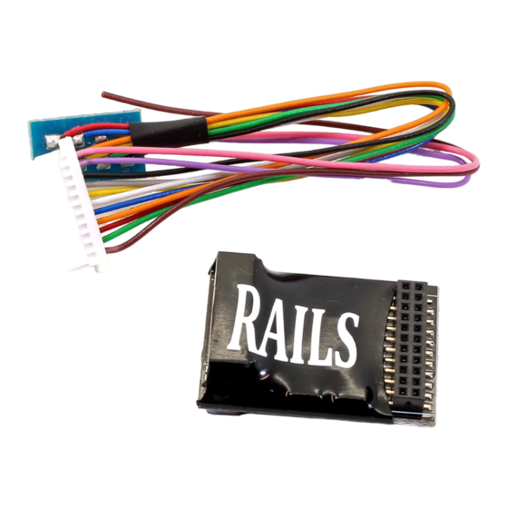
Insert the decoder. Note that 21 pin decoders install with the PCB side down and you should press down firmly but
evenly so the pins engage evenly. 6 pin decoders are installed with the RAILS logo on top and 8 -pin direct decoders
are installed correctly when the #1 pin of the socket is at the same end as the S in the RAILS logo. For 8 -pin harness
decoders, the number 1 pin is the orange wire on the 8 -pin plug.
BEFORE you attempt to run your locomotive on the layout.
After installation, always place your loco onto the programming track first. This is always a good idea as the lower power of
the program track will not cause damage if the loco wiring is faulty. If your decoder won't respond on the programming
track, check the installation.
ADDRESS your new RAILS CONNECT DCC decoder.
The default address is 3. RAILS CONNECT decoders can be set at any address between 1 and 9999. Use your controller
instructions.
RESET and additional setup or adjustment of your decoder.
Set CV8 to 8 to restore ex -factory defaults. Your decoder has a huge range of features. The following pages detail the
extended range of CV settings that can be adjusted on your decoder.
CONTENTS
Product Specification
Long Address
Decoder Lock
Modifying Light Effects
Flicker Effects
DC Light Operation
Momentum
3 Point Speed Curves
Button Control of Motor
2
Short Address
2
Consist Address
2
Light Effects
3
Function Remapping
6
Consist Light Control
7
Back EMF
8
Variable Momentum
8
Speed Tables
9
Full CV Listing
2
2
3
6
7
7
8
9
10
1
V1—10-10-20—RB
Advertisement

Summary of Contents for RAILS CONNECT RoS-8D
- Page 1 ADDRESS your new RAILS CONNECT DCC decoder. The default address is 3. RAILS CONNECT decoders can be set at any address between 1 and 9999. Use your controller instructions. RESET and additional setup or adjustment of your decoder.
- Page 2 CV guide and specification for RoS-8D, RoS-218, RoS-6D & RoS-8HP decoders Specification (RoS-8D, RoS-218, RoS-6D) Continuous Power 750mA (Continuous) Peak Power 1.0A Light Function output max 100mA Version V9-B3 Specification (RoS-8HP) Continuous Power 1.5mA (Conservative, RMS) Peak Power 3.0A (Momentary peak only)
- Page 3 CV guide and specification for RoS-8D, RoS-218 and RoS-6D decoders 5、Light effects Light feature Light function Forward Reverse Both CV49 White wire CV50 Yellow wire Constant Bright CV51 Green wire Random Flicker CV52 Purple wire Mars Light CV53 Pink wire...
- Page 4 CV guide and specification for RoS-8D, RoS-218 and RoS-6D decoders Mars Light, Gyra Light, and Rotary Beacon Modification: • Note: All of the above lighting features allow for 3 points of brightness adjustment, as well as 2 timing related CV’s.
- Page 5 CV guide and specification for RoS-8D, RoS-218 and RoS-6D decoders 6.6、Rule 17 (dimmable light) Rule 17 Dimming includes three different types of functionality: Opposite Dim (when travel- ling forward the reverse light is on dimmed, and when travelling in reverse the forward light is on dimmed), Dim when stopped (when a locomotive comes to a complete stop the light(s) dim), and button controlled dimming.
- Page 6 CV guide and specification for RoS-8D, RoS-218 and RoS-6D decoders 7、Function Remapping In most cases, you can control almost any wire ( function ) with almost any button on your controller. R-0-F Default CV White wire CV33 Yellow wire CV34...
- Page 7 CV guide and specification for RoS-8D, RoS-218 and RoS-6D decoders 9、Consist Light Control WhiteF(0)F GreenF(1) YellowF(0)R PurpleF(2) CV22 BrownF(3) PinkF(4) CV21 By default none of the lights controlled by a decoder can be turned on or off when using the consist address to identify the locomotive.
- Page 8 CV guide and specification for RoS-8D, RoS-218 and RoS-6D decoders 11.3、BEMF Cutout To enable BEMF Cutout simply enter a value into CV 10 that is between 1 and 128. The value entered into CV 10 directly correlates to the speed step at which it will cut out. That is to say if you wish to disable BEMF at speed steps above speed step 50 enter a value of 50 into CV 10.
- Page 9 CV guide and specification for RoS-8D, RoS-218 and RoS-6D decoders 15、Speed Tables Speed steps Step1 Step2 Step3 .... Step126 Step127 Step128 .... To enable user speed tables add a value of 16 to whatever value you find in CV 29.
- Page 10 CV guide and specification for RoS-8D, RoS-218 and RoS-6D decoders 16、CVs and Description Description Default Description Default Primary Address Function 4Map (Pink0-6) Vstart Function 3Map (Brown7-12) Acceleration Function 4Map (Pink7-12) Deceleration Not in Use Vhigh Not in Use Vmid Not in Use...
- Page 11 CV guide and specification for RoS-8D, RoS-218 and RoS-6D decoders 16、CVs and Description (continued) Description Default Description Default Step 13SpeedTable DecelerationRate2 Step 14Speed Table Rate3EndingPoint Step 15Speed Table DecelerationRate3 Step 16Speed Table Rate2 Start point Step 17Speed Table Acceleration Rate 2...
Need help?
Do you have a question about the RoS-8D and is the answer not in the manual?
Questions and answers