Advertisement
Quick Links
Advertisement

Summary of Contents for ATM Technologies BAFANG BBS01
- Page 1 BAFANG BBS01/BBS02 Installation Manual...
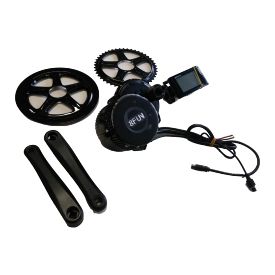
- Page 2 System Overview...
- Page 3 Speed Sensor Magnet Display Speed Sensor Mid-Drive Motor...
- Page 4 Technical Paramete 250W, Motor Installation Diagrams...
-
Page 7: Installation Procedures
Installation Procedures 1. Open the package and take out the drive unit and accessories. Check whether the specifications of the motor are correct. Check that all accessories and wiring have been included in the box as per the packing list. 2. - Page 8 Make sure the thread of the axle tube extends beyond the bottom bracket more than 10mm. Please note that for 73mm bottom brackets this may be less. Axle Thread 4. With the teeth on the fixing plate facing inwards, fix the plate on the drive unit with 2 pieces of M6 x 10mm bolt.
- Page 9 5. Hold the drive unit up against the frame and tighten the M6 x 10mm bolts and M33 nut simultaneously. Tighten M33 with force 30-40Nm. If you purchased an installation toolkit use the BBB Lockring tool. M33 Nut 6. Once this has been tightened fit the BB cup over theM33 (20-30Nm)
- Page 10 7. Fix the LH crank on the bike with the M8 inner hex bolt. Tightening force 35-40Nm. Use Loctite if you wish as this bolt is prone to loosening. LH Crank M8 Nut 8. Fix the RH crank on the bike with the M8 inner hex bolt. Tightening force 35-40Nm. Use Loctite if you wish as this bolt is prone to loosening.
- Page 11 9. Connect waterproof harness, Anderson connectors for battery and the speed sensor to the motor unit. Waterproof Wiring Harness Anderson Battery Connectors (You may choose your own connectors provided they have a similar current rating of 40a) Speed Sensor – Optimal position of magnet is less than 5mm from Sensor on rear wheel.
- Page 12 10. Speed Sensor Mounting.The images below give a clearer indication on how to mount the magnet and sensor. Sensor design may vary from images below.
- Page 13 11. Component Connection Diagram A – Brake Cuttoff / Magnetic Sensor Plugs (2) – Yellow – Female At Harness B – C961 Display – Green – Male at Harness C – Throttle – Yellow – Male at Harness D – Main Harness waterproof connection E –...
- Page 14 12. Location of Display, Throttle, On/Off & PAS Controls. The image below shows a common setup with the throttle on the left hand side. You will need to remove grips and other components to install these. C961 Display Throttle On/Off, PAS Control...
-
Page 15: Packing List
Packing List BBS01 / 02 Motor Display Brakes / Cutoff Sensor (2 pieces) EB-BUS Cable Fixing Plate (with teeth) Chain Wheel and Chan Whee Cover Cranks (2 pieces) M5 x 10mm Nut (5 pieces) M6 x 12mm Nut (2 pieces) M33 Nut And Cup (2 Pieces) ST 3.7 Nut (2 Pieces) Speed Detection Sensor...
Need help?
Do you have a question about the BAFANG BBS01 and is the answer not in the manual?
Questions and answers