Table of Contents
Advertisement
Available languages
Available languages
Quick Links
Advertisement
Chapters
Table of Contents

Subscribe to Our Youtube Channel
Summary of Contents for TATRA TPI 05 D.V
- Page 1 COMBI STEAM OVENS BAKERY OVENS Instruction Manual Bedienungsanleitung 50LIB001...
-
Page 2: Table Of Contents
E n g l i s h INDEX: page INSTRUCTIONS FOR THE INSTALLER WARNING PRELIMINARY OPERATIONS III. INSTALLATION AREA PREPARING FOR INSTALLATION ELECTRICAL CONNECTION WATER CONNECTION VII. FUMES DISCHARGE VIII. STACKING OVENS SPECIFICATIONS INSTRUCTIONS FOR THE USER WARNING TESTING III. ORDINARY MAINTENANCE EXTRAORDINARY MAINTENANCE MAINTENANCE IN CASE OF BREAKAGE... -
Page 3: Instructions For The Installer
E n g l i s h INSTRUCTIONS FOR THE INSTALLER WARNING Read this instructions booklet carefully before starting the installation and start-up operations. All installation, assembly, assistance and extraordinary maintenance shall be carried out by qualified personnel and supplied with necessary professional (authorizations by the manufacturer or retailer), in accordance with local laws in effect where installation takes place regarding product and workplace safety. -
Page 4: Preparing For Installation
E n g l i s h IV. PREPARING FOR INSTALLATION Remove the outer packaging (wooden or carton box) and dispose it in compliance with the laws in force in the country of installation. REMOVING PROTECTIVE FILM ETC. Remove the protection film from the external and internal walls. - Page 5 E n g l i s h APPLIANCE NOT SUPPLIED WITH CABLE WITH THREE PHASE TERMINALS Articles supplied by us come with terminals such as in the image. To connect to the mains see the label in the manual and stuck to the lower part of the back of the appliance near the Information Plate .
- Page 6 E n g l i s h Check there is no static discharge between live and earth. Check the limit switch continuity between the external casing and the earth wire of the mains. It is advised to use a multi tester to carry out these operations.
-
Page 7: Water Connection
E n g l i s h CABLE SUBSTITUTION This must be carried out by a qualified authorised technician. The earth wire must always be yellow green. WARNING: the yellow/green voltage wires in the earth cable must be 3cm longer than the others. -
Page 8: Fumes Discharge
E n g l i s h The inflowing water shall have a pressure value comprised between 150 (1,5 bar) and 200 kPa (2bar) and a maximum temperature of 30°C. If the inflow pressure value exceeds 200kPa (2bar), a pressure reducer will have to be installed, calibrated at 200kPa (2 bar). DRAINAGE CONNECTION Water flowing out from the oven drainage system may reach high temperatures (90°). -
Page 9: Instructions For The User
E n g l i s h Art./Model: model according to customer classification Ref: model according to internal manufacturer’s classification Ser. N °: identification number, different for each product TYPE: product model according to its technical properties Information: IPX4 protection level against water sprays / kPa….inflow water pressure / production year. -
Page 10: Testing
E n g l i s h When not in use for extended periods (for example 12 hours) it is advisable to leave the door slightly open. If it is not in use for long periods of time (many days) it is advisable to turn it off at the mains and disconnect it from the water supply. -
Page 11: Ordinary Maintenance
E n g l i s h | 10 III. ORDINARY MAINTENANCE The user is solely responsible for ordinary maintenance. The Assistence Centre must be contacted for extraordinary maintenance which requires a specialized authorized technician. Before cleaning, disconnect the device from the power supply and wait until it is fully cold. -
Page 12: Extraordinary Maintenance
E n g l i s h | 11 “B” with one having the same • characteristics. Screw back on glass cover “A” • while observing washer “C”. • Put the side grids back on ensuring they are well fitted. Should the glass lid be broken or damaged, do not use the oven until the lid is replaced (Contact the Assistence Centre). -
Page 13: Advice During Cooking
E n g l i s h | 12 Contact specialised technician for repair Failure of one of the resistances (Assistance Service ). Supply voltage failure Restore power supply voltage Incorrect connection to the power Check connection to the power supply The oven is completely OFF supply network network... -
Page 14: Mechanical Oven Control Panel
E n g l i s h | 13 STEAM The humidification system is recommended for more delicate coking of all types of foods. Furthermore, it is recommended quick defrosting, warming food products without dehydrating or hardening them and for naturally desalting foods preserved by salting. The combination of the steaming function with the conventional ones allows flexibility of use and saving energy and time, simultaneously maintaining the nutritious and taste qualities of the food unaltered. -
Page 15: Multifunction Oven Control Panel
E n g l i s h | 14 TIMER SELECTOR When manual is selected, the oven stays on until someone turns it off.When a certain value is selected, the oven stays on for that time (120 minutes maximum). ... -
Page 16: Digital Oven Control Panel
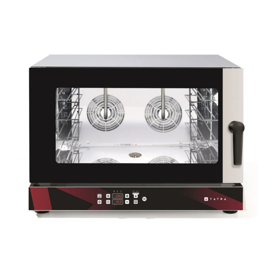
E n g l i s h | 15 TIMER SELECTOR When manual is selected, the oven stays on until someone turns it off. When a certain value is selected, the oven stays on for that time (120 minutes maximum). ... - Page 17 E n g l i s h | 16 START / STOP cooking light START / STOP cooking CELSIUS led Speed regulation FAHRENHEIT led Increase button Temperature selector Decrease button ON/OFF When power is supplied to the oven the control panel lights up and the operating display indicates temperature in cooking chamber.The oven now is ready for operating.
- Page 18 E n g l i s h | 17 • COOKING CYCLE The oven is suitable for 3 different cooking phases for each cooking program (1,2,3). • COOKING CYCLE LED The led that is on will show you in which cooking phase is operating (1,2,3). •...
- Page 19 E n g l i s h | 18 - Select the time button and with +/- introduce the value desired + press the the time button for confirmation. - Select the Steam button and with +/- introduce the value desired + press the the Steam button for confirmation.
- Page 20 D e u t s c h INHALTSVERZEICHNIS: Seite ANLEITUNG FÜR DEN INSTALLATEUR HINWEISE VORBEREITUNGEN III. INSTALLATIONSORT VORBEREITUNG ZUR INSTALLATION ELEKTRISCHER ANSCHLUSS WASSERANSCHLUSS VII. ANSCHLUSS DER ABLUFT ÜBEREINANDERSTELLEN VON ÖFEN TECHNISCHE DATEN ANLEITUNG FÜR DEN BENUTZER HINWEISE ERSTER GEBRAUCH III. REGELMÄßIGE WARTUNG AUSSERORDENTLICHE WARTUNG INSTANDSETZUNG BEI STÖRUNGEN...
-
Page 21: Anleitung Für Den Installateur
D e u t s c h ANLEITUNG FÜR DEN INSTALLATEUR HINWEISE Diese Betriebs- und Installationsanleitung ist vor der Installation und Inbetriebnahme des Gerätes sorgfältig zu lesen. Alle Arbeiten, die Installation, Montage, Kundendienst und außerordentliche Wartung betreffen, dürfen nur von qualifiziertem Personal mit den erforderlichen fachlichen Anforderungen (Autorisierung vom Hersteller oder Verkäufer) durchgeführt werden. -
Page 22: Vorbereitung Zur Installation
D e u t s c h Mindestabstände einzuhalten: 50 cm seitlich und über dem Gerät und 70 cm auf der Rückseite des Ofens. Unter keinen Umständen darf der Ofen in der Nähe von entflammbaren Materialien oder Behältern mit entflammbarem Inhalt (wie Wände, Möbel, Trennwände oder Gasflaschen) positioniert werden. Sollte dies nicht möglich sein, sind die betreffende Teile mit nicht entflammbaren, wärmedämmenden Materialien zu verkleiden und die Brandschutzverordnungen genauestens zu befolgen. - Page 23 D e u t s c h ÖFEN MIT EINPHASIGEM KABEL UND STECKER Bei Geräten, die mit Kabel und Stecker ausgerüstet sind (220- 240 V einphasig), muss nur der Stecker in eine entsprechende Steckdose eingesteckt werden (die kompatibel zum gelieferten Stecker und zum Stromfluss sein muss, siehe Typenschild).
- Page 24 D e u t s c h und Brücke fest verbunden sind. Auf dem Etikett wird für jedes Anschlussschema der zu verwendende Kabeltyp (HO7RN-F) und die Querschnitte der Adern in angegeben. mm² • ( A4 ) Den unteren Teil der Abdeckung wieder anbringen und festschrauben und das Kabel durch Anziehen der Kabelverschraubung befestigen.
- Page 25 D e u t s c h AUSTAUSCH DES NETZKABELS Diese Arbeit muss von qualifiziertem und autorisiertem Personal ausgeführt werden. Das Erdungskabel muss immer die grün-gelbe Farbe haben. ACHTUNG: Der grün-gelbe Schutzleiter der elektrischen Verbindungsleitung muss mindestens 3 cm länger als die anderen Leiter sein.
-
Page 26: Wasseranschluss
D e u t s c h Bei Klemmen mit vorinstalliertem Kabel dessen Austausch wie folgt vornehmen: • ( A1 ) Die Kabelverschraubung lösen und den unteren Teil der hinteren Abdeckung des Gerätes durch Entfernen der Schrauben abnehmen. • ( A3 ) Die Klemmschrauben der Klemme lösen und die Adern des Versorgungskabels herausziehen. -
Page 27: Anschluss Der Abluft
D e u t s c h zwischen 150 (1,5 bar) und 200 kPa (2 bar) und eine Maximaltemperatur von 30°C haben. Falls der Wasserdruck über 200 kPa (2 bar) liegt, muss ein auf 200 kPa (2 bar) eingestellter Druckminderer installiert werden. -
Page 28: Übereinanderstellen Von Öfen
D e u t s c h VIII. ÜBEREINANDERSTELLEN VON ÖFEN Sollen mehrere Öfen übereinander gestellt werden, muss zwingend der entsprechende Zubehörsatz verwendet werden, um den korrekten Abstand zwischen zwei Öfen zu wahren. TECHNISCHE DATEN TYPENSCHILD INFORMATIONE LEISTUNGSAUFNAHM FREQUENZ GEWICHT STROMVERSORG STROMVERSORGUNG Art./Modell:... -
Page 29: Anleitung Für Den Benutzer
D e u t s c h | 10 ANLEITUNG FÜR DEN BENUTZER I. HINWEISE Die Bedienungsanleitung ist sorgfältig zu lesen, da nachstehend Angaben zur Sicherheit und zum Gebrauch des Gerätes gemacht werden. Für späteres Nachschlagen sorgfältig aufbewahren. Falsches Vorgehen bei Installation, Kundendienst, Wartung, Gebrauch und Reinigung oder eventuelle Veränderungen oder Manipulationen des Produktes können Fehlfunktionen, Schäden und Verletzungen hervorrufen. -
Page 30: Erster Gebrauch
D e u t s c h | 11 Manipulationen auch nur eines Teils des Gerätes oder auf Verwendung von nicht originalen Ersatzteilen beruhen. Dieses Gerät entspricht den geltenden EU-Richtlinien. Vor Inbetriebnahme des Gerätes sind gewissenhaft alle notwendigen Kontrollen durchzuführen, um sicherzustellen, dass sowohl die Anlagen als auch die Installation des Gerätes den gesetzlichen Normen und den technischen- und Sicherheitshinweisen dieser Bedienungsanleitung entspricht. -
Page 31: Regelmäßige Wartung
D e u t s c h | 12 Im Garraum dürfen keine Rückstände von Lösungs- oder Reinigungsmitteln verbleiben. Deren Entfernung sollte durch gründliches Spülen mit einem feuchten Lappen erfolgen, dabei Augen, Mund und Hände angemessen schützen. Mögliche Gefahr der Korrosion. Den leeren Ofen für ca. -
Page 32: Ausserordentliche Wartung
D e u t s c h | 13 AUSTAUSCH DER GLÜHBIRNE DER BELEUCHTUNG ACHTUNG: Um Stromschläge oder Personenschäden zu vermeiden, ist folgende Anweisung streng zu befolgen: • Den Ofen abkühlen lassen und die Netzverbindung unterbrechen. • Die seitlichen Führungsschienen für die Backbleche herausnehmen. •... -
Page 33: Instandsetzung Bei Störungen
D e u t s c h | 14 V. INSTANDSETZUNG BEI STÖRUNGEN Bei Störungen ist die Stromversorgung des Gerätes zu trennen und die Wasserversorgung zu unterbrechen. Vor der Verständigung des Kundendienstes sind die in der Tabelle beschriebenen Kontrollen durchzuführen (siehe unten). STÖRUNG URSACHE ABHILFE... -
Page 34: Empfehlungen Zum Garen
D e u t s c h | 15 Falls die Störung nicht behoben werden kann, bitte den Händler oder Hersteller benachrichtigen und einen Einsatz des Kundendienstes anfordern. Bitte Artikel (Art.) und Seriennummer (Ser N°) des Gerätes mitteilen. Diese Daten befinden sich auf dem TYPENSCHILD auf der Geräterückseite ERSATZTEILE Es dürfen nur zugelassene Bauteile verwendet werden. - Page 35 D e u t s c h | 16 Gebrauch mit Einsparung von Zeit und Energie, unter Wahrung des Nährwerts und des Geschmacks der Lebensmittel. Dieses System zum Garen ist für alle Arten von Speisen ideal. Das in das Gebläse gesprühte Wasser wird zerstäubt und vom Heizelement in Dampf umgewandelt.
- Page 36 D e u t s c h | 17 • ZEITWÄHLER Bei manueller Einstellung bleibt der Ofen für unbegrenzte Zeit eingeschaltet, bis der Benutzer eingreift. Ist eine Zeitspanne vorgewählt, bleibt der Ofen für diese Zeit eingeschaltet (max. 120 Minuten). • TEMPERATURWÄHLER Dieser Regler dient zum Einstellen der gewünschten Temperatur.
- Page 37 D e u t s c h | 18 BEDIENFELD MULTIFUNKTIONSOFEN III. Wahlschalter Temperatur Taste Befeuchtung Wahlschalter Garmodus Auftauen Wahlschalter Timer Heißluft Encoder für "+/-" Einstellung Grill Kontrollleuchte Thermostat Grill + Umluft • ZEITWÄHLER Bei manueller Einstellung bleibt der Ofen für unbegrenzte Zeit eingeschaltet, bis der Benutzer handelt.
- Page 38 D e u t s c h | 19 Bei Einstellung Grill funktioniert das Heizsystem des Ofens in Abhängigkeit der Temperaturwahl des Thermostats. Nur das Heizelement des Grills ist in Funktion, das kreisförmige Heizelement um die Gebläse ist ausgeschaltet. Bei Einstellung Grill + Umluft funktioniert das Heizsystem des Ofens in Abhängigkeitder Temperaturwahl des Thermostats.
- Page 39 D e u t s c h | 20 eingestellte Wert wird gespeichert, und auf dem Display wird die Innentemperatur des Garraumes angezeigt. Einstellbereich von 30 °C bis 260 °C. Während des Betriebs wird auf dem Display GARRAUM die effektive Innentemperatur angezeigt, zum Anzeigen der eingestellten Temperatur die Taste zur Temperaturwahl drücken.
- Page 40 D e u t s c h | 21 LED CELSIUS / FAHRENHEIT Diese LED zeigt an, welche Gradskala aktiv ist (Celsius oder Fahrenheit) GAREN MIT PROGRAMMEN Um ein Programm für einen Garvorgang auszuwählen, die Taste PROGRAMME drücken und mit den Tasten (+) oder (-) das gewünschte Programm auswählen.
- Page 41 D e u t s c h | 22 - Taste <Befeuchten> drücken und mit <+>/<-> die gewünschte Feuchtigkeit einstellen, mit <Befeuchten> bestätigen - Taste <Phasen> betätigen, um zur zweiten Phase zu wechseln (im Fall eines mehrphasigen Garprozesses), LED Nr. 2 leuchtet. Nun kann Zeit, Temperatur und Feuchtigkeit wie oben beschrieben programmiert werden und zur Phase Nr.
- Page 42 COMBI STEAM OVENS BAKERY OVENS Instruction Manual Notice d’utilisation 50LIB001...
- Page 43 E n g l i s h INDEX: page INSTRUCTIONS FOR THE INSTALLER WARNING PRELIMINARY OPERATIONS III. INSTALLATION AREA PREPARING FOR INSTALLATION ELECTRICAL CONNECTION WATER CONNECTION VII. FUMES DISCHARGE VIII. STACKING OVENS SPECIFICATIONS INSTRUCTIONS FOR THE USER WARNING TESTING III. ORDINARY MAINTENANCE EXTRAORDINARY MAINTENANCE MAINTENANCE IN CASE OF BREAKAGE...
- Page 44 E n g l i s h INSTRUCTIONS FOR THE INSTALLER WARNING Read this instructions booklet carefully before starting the installation and start-up operations. All installation, assembly, assistance and extraordinary maintenance shall be carried out by qualified personnel and supplied with necessary professional (authorizations by the manufacturer or retailer), in accordance with local laws in effect where installation takes place regarding product and workplace safety.
- Page 45 E n g l i s h IV. PREPARING FOR INSTALLATION Remove the outer packaging (wooden or carton box) and dispose it in compliance with the laws in force in the country of installation. REMOVING PROTECTIVE FILM ETC. Remove the protection film from the external and internal walls.
- Page 46 E n g l i s h APPLIANCE NOT SUPPLIED WITH CABLE WITH THREE PHASE TERMINALS Articles supplied by us come with terminals such as in the image. To connect to the mains see the label in the manual and stuck to the lower part of the back of the appliance near the Information Plate .
- Page 47 E n g l i s h Check there is no static discharge between live and earth. Check the limit switch continuity between the external casing and the earth wire of the mains. It is advised to use a multi tester to carry out these operations.
- Page 48 E n g l i s h CABLE SUBSTITUTION This must be carried out by a qualified authorised technician. The earth wire must always be yellow green. WARNING: the yellow/green voltage wires in the earth cable must be 3cm longer than the others.
- Page 49 E n g l i s h The inflowing water shall have a pressure value comprised between 150 (1,5 bar) and 200 kPa (2bar) and a maximum temperature of 30°C. If the inflow pressure value exceeds 200kPa (2bar), a pressure reducer will have to be installed, calibrated at 200kPa (2 bar). DRAINAGE CONNECTION Water flowing out from the oven drainage system may reach high temperatures (90°).
- Page 50 E n g l i s h Art./Model: model according to customer classification Ref: model according to internal manufacturer’s classification Ser. N °: identification number, different for each product TYPE: product model according to its technical properties Information: IPX4 protection level against water sprays / kPa….inflow water pressure / production year.
- Page 51 E n g l i s h When not in use for extended periods (for example 12 hours) it is advisable to leave the door slightly open. If it is not in use for long periods of time (many days) it is advisable to turn it off at the mains and disconnect it from the water supply.
- Page 52 E n g l i s h | 10 III. ORDINARY MAINTENANCE The user is solely responsible for ordinary maintenance. The Assistence Centre must be contacted for extraordinary maintenance which requires a specialized authorized technician. Before cleaning, disconnect the device from the power supply and wait until it is fully cold.
- Page 53 E n g l i s h | 11 “B” with one having the same • characteristics. Screw back on glass cover “A” • while observing washer “C”. • Put the side grids back on ensuring they are well fitted. Should the glass lid be broken or damaged, do not use the oven until the lid is replaced (Contact the Assistence Centre).
- Page 54 E n g l i s h | 12 Contact specialised technician for repair Failure of one of the resistances (Assistance Service ). Supply voltage failure Restore power supply voltage Incorrect connection to the power Check connection to the power supply The oven is completely OFF supply network network...
- Page 55 E n g l i s h | 13 STEAM The humidification system is recommended for more delicate coking of all types of foods. Furthermore, it is recommended quick defrosting, warming food products without dehydrating or hardening them and for naturally desalting foods preserved by salting. The combination of the steaming function with the conventional ones allows flexibility of use and saving energy and time, simultaneously maintaining the nutritious and taste qualities of the food unaltered.
- Page 56 E n g l i s h | 14 TIMER SELECTOR When manual is selected, the oven stays on until someone turns it off.When a certain value is selected, the oven stays on for that time (120 minutes maximum). ...
- Page 57 E n g l i s h | 15 TIMER SELECTOR When manual is selected, the oven stays on until someone turns it off. When a certain value is selected, the oven stays on for that time (120 minutes maximum). ...
- Page 58 E n g l i s h | 16 START / STOP cooking light START / STOP cooking CELSIUS led Speed regulation FAHRENHEIT led Increase button Temperature selector Decrease button ON/OFF When power is supplied to the oven the control panel lights up and the operating display indicates temperature in cooking chamber.The oven now is ready for operating.
- Page 59 E n g l i s h | 17 • COOKING CYCLE The oven is suitable for 3 different cooking phases for each cooking program (1,2,3). • COOKING CYCLE LED The led that is on will show you in which cooking phase is operating (1,2,3). •...
- Page 60 E n g l i s h | 18 - Select the time button and with +/- introduce the value desired + press the the time button for confirmation. - Select the Steam button and with +/- introduce the value desired + press the the Steam button for confirmation.
- Page 61 F r a n ҫ a i s TABLE DES MATIERES: page INSTRUCTIONS POUR L’INSTALLATEUR AVERTISSEMENTS OPERATIONS PRELIMINAIRES LIEU D’INSTALLATION III. PREDISPOSITION A L’INSTALLATION RACCORDEMENT ELECTRIQUE RACCORDEMENT HYDRIQUE VII. RACCORDEMENT EVACUATIONS SUPERPOSITION DE FOURS DONNEES TECHNIQUES INSTRUCTIONS POUR L’UTILISATEUR AVERTISSEMENTS PREMIERE UTILISATION ENTRETIEN ORDINAIRE ENTRETIEN EXTRAORDINAIRE...
-
Page 62: Instructions Pour L'installateur
F r a n ҫ a i s INSTRUCTIONS POUR L’INSTALLATEUR AVERTISSEMENTS Lire attentivement ce livret avant d’entamer les opérations d’installation et de mise en fonction. Toutes les opérations d’installation, montage, assistance et entretien extraordinaire doivent être effectuées par du personnel qualifié et ayant les critères professionnels nécessaires (autorisé... -
Page 63: Predisposition A L'installation
F r a n ҫ a i s IV. PREDISPOSITION A L’INSTALLATION Enlever l’emballage externe (caisse en bois et/ou boîte en carton) et l’éliminer selon la normative en vigueur dans le pays d’installation. ELIMINATION DE LA PELLICULE DE PROTECTION ET AUTRE Enlever complètement la pellicule de protection des parois externes et internes (voir image à... - Page 64 F r a n ҫ a i s On peut seulement remplacer le câble: cette opération doit être effectuée par un technicien qualifié et autorisé. Le câble de mise à la terre doit toujours être de couleur jaune vert. APPAREILS SANS CABLE ET EQUIPES D’UNE BORNE TRIPHASEE Les articles que nous fournissons sont équipés d’une borne comme sur la figure.
- Page 65 F r a n ҫ a i s Un mauvais raccordement peut causer une surchauffe de la borne, ce qui peut la fondre et entraîner des risques de décharges électriques. Vérifier que tous les raccordements électriques sont bien serrés avant de raccorder le four au circuit électrique.
-
Page 66: Raccordement Hydrique
F r a n ҫ a i s REMPLACEMENT DU CABLE ELECTRIQUE DE RACCORDEMENT Cette opération doit être effectuée par un technicien qualifié et autorisé. Le câble de mise à la terre doit toujours être de couleur jaune vert. ATTENTION: dans le câble électrique de raccordement, le conducteur de terre jaune/vert doit être plus long d’au moins 3 cm par rapport aux autres conducteurs. -
Page 67: Raccordement Evacuations
F r a n ҫ a i s zone marquée avec une étiquette, le four possède une entrée G 3/4 '' avec un filtre. L’eau en entrée doit avoir une valeur de pression comprise entre 150 (1,5 bar) et 200 kPa (2bar) et une température maximale de 30°C. -
Page 68: Donnees Techniques
F r a n ҫ a i s IX. DONNEES TECHNIQUES INFORMATIONS PUISSANCE ABSORBEE FREQUENCE ALIMENTATION POIDS ALIMENTATION Art. Modéle.: modèle selon la classification du client Réf. modèle selon la classification interne du producteur Ser. N numéro d’identification, différent pour chaque produit °... -
Page 69: Instructions Pour L'utilisateur
F r a n ҫ a i s INSTRUCTIONS POUR L’UTILISATEUR AVERTISSEMENTS Lire attentivement le manuel suivant puisqu'il fournit des indications sur la sécurité et l'utilisation de l'appareil. Le conserver avec soin pour toute consultation ultérieure. Une mauvaise installation, assistance, entretien, utilisation, nettoyage et d'éventuelles altérations ou modifications peuvent être la cause de dysfonctionnements, dommages et lésions. -
Page 70: Premiere Utilisation
F r a n ҫ a i s | 10 Les parties externes du four peuvent dépasser la température de 60°C, donc pour éviter le risque de brûlures, il est conseillé de ne pas toucher les zones ou les pièces présentant le symbole à... -
Page 71: Entretien Ordinaire
F r a n ҫ a i s | 11 PREMIER NETTOYAGE CHAMBRE DE CUISSON DU FOUR Avant d’effectuer toute intervention de nettoyage, il faut débrancher l’alimentation électrique de l’appareil et attendre la fin du refroidissement complet. ATTENTION: l’appareil ne doit jamais être nettoyé avec des jets d’eau ou de vapeur sous pression. -
Page 72: Entretien Extraordinaire
F r a n ҫ a i s | 12 En cas d’incrustations de saleté, utiliser uniquement des spatules en plastique ou une éponge imprégnée de vinaigre et eau tiède. Attention: s’il y a des graisses et des résidus alimentaires dans la chambre de combustion, ils pourraient prendre feu durant l’utilisation du four;... -
Page 73: Entretien En Cas De Panne
F r a n ҫ a i s | 13 ENTRETIEN EN CAS DE PANNE En cas de panne, débrancher le dispositif de l’alimentation électrique et fermer l’alimentation en eau. Avant de téléphoner au Centre d’Assistance clients, vérifier ce qui est décrit dans le tableau (voir ci-dessous). -
Page 74: Conseils Pendant La Cuisson
F r a n ҫ a i s | 14 code (Art.) et numéro de série (Ser N) de l’appareil en votre possession. Ces données se trouvent sur la PLAQUETTE DONNÉES à l’arrière de la machine. PIECES DE RECHANGE Il faut utiliser uniquement des pièces autorisées. Toutes les interventions doivent être effectuées par du personnel technique spécialisé... - Page 75 F r a n ҫ a i s | 15 maintenant inaltérées les qualités nutritives et la saveur des aliments. C’est un système de cuisson idéal pour tous les types d’aliments. L’eau injectée sur le ventilateur, est nébulisée et en passant à travers la résistance, elle se transforme en vapeur.
- Page 76 F r a n ҫ a i s | 16 BOUTON TIMER Quand est sélectionnée l’option manuel, le four reste toujours allumé, pour une durée infinie jusqu’à l’intervention de l’opérateur. Quand une certaine valeur est sélectionnée, le four reste allumé pour cette quantité de temps (maximum 120 minutes).
-
Page 77: Panneau De Commandes Four Multifunction
F r a n ҫ a i s | 17 VIII. PANNEAU COMMANDES FOUR MULTIFUNCTION Poignée température Bouton humidification Poignée sélecteur cuisson Defrost Poignée timer Convention Voyant thermostat Grill Voyant thermostat Grill + ventilateur BOUTON TIMER Quand est sélectionnée l’option manuel, le four reste toujours allumé, pour une durée infinie jusqu’à... - Page 78 F r a n ҫ a i s | 18 4) Lorsqu'elle est définie GRILL, au four, système de chauffage est sur et contrôlée par le bouton du thermostat. Seul l'élément de chauffage grill travaille, tandis que la résistance circulante autour les fans est éteint. 5) Quand il est défini sur GRILL + CONVETION le four, système de chauffage est allumé...
- Page 79 F r a n ҫ a i s | 19 température réelle chambre interne et pour voir la température réglée, vous devez appuyer sur bouton « température ». Élément conduit de chauffage est sur vert et rouge lorsque la chaleur est activé...
- Page 80 F r a n ҫ a i s | 20 PROGRAMMES DE CUISSON Pour programmer une cuisson processus Appuyez sur le bouton et agir sur + / - vous pouvez sélectionner le programme à définir. Après avoir sélectionné le programme numéro de confirmer en appuyant sur le bouton de programme de cuisson.
- Page 81 COMBI STEAM OVENS BAKERY OVENS Instruction Manual Manuale di Istruzioni 50LIB001...
- Page 82 E n g l i s h INDEX: page INSTRUCTIONS FOR THE INSTALLER WARNING PRELIMINARY OPERATIONS III. INSTALLATION AREA PREPARING FOR INSTALLATION ELECTRICAL CONNECTION WATER CONNECTION VII. FUMES DISCHARGE VIII. STACKING OVENS SPECIFICATIONS INSTRUCTIONS FOR THE USER WARNING TESTING III. ORDINARY MAINTENANCE EXTRAORDINARY MAINTENANCE MAINTENANCE IN CASE OF BREAKAGE...
- Page 83 E n g l i s h INSTRUCTIONS FOR THE INSTALLER WARNING Read this instructions booklet carefully before starting the installation and start-up operations. All installation, assembly, assistance and extraordinary maintenance shall be carried out by qualified personnel and supplied with necessary professional (authorizations by the manufacturer or retailer), in accordance with local laws in effect where installation takes place regarding product and workplace safety.
- Page 84 E n g l i s h IV. PREPARING FOR INSTALLATION Remove the outer packaging (wooden or carton box) and dispose it in compliance with the laws in force in the country of installation. REMOVING PROTECTIVE FILM ETC. Remove the protection film from the external and internal walls.
- Page 85 E n g l i s h APPLIANCE NOT SUPPLIED WITH CABLE WITH THREE PHASE TERMINALS Articles supplied by us come with terminals such as in the image. To connect to the mains see the label in the manual and stuck to the lower part of the back of the appliance near the Information Plate .
- Page 86 E n g l i s h Check there is no static discharge between live and earth. Check the limit switch continuity between the external casing and the earth wire of the mains. It is advised to use a multi tester to carry out these operations.
- Page 87 E n g l i s h CABLE SUBSTITUTION This must be carried out by a qualified authorised technician. The earth wire must always be yellow green. WARNING: the yellow/green voltage wires in the earth cable must be 3cm longer than the others.
- Page 88 E n g l i s h The inflowing water shall have a pressure value comprised between 150 (1,5 bar) and 200 kPa (2bar) and a maximum temperature of 30°C. If the inflow pressure value exceeds 200kPa (2bar), a pressure reducer will have to be installed, calibrated at 200kPa (2 bar). DRAINAGE CONNECTION Water flowing out from the oven drainage system may reach high temperatures (90°).
- Page 89 E n g l i s h Art./Model: model according to customer classification Ref: model according to internal manufacturer’s classification Ser. N °: identification number, different for each product TYPE: product model according to its technical properties Information: IPX4 protection level against water sprays / kPa….inflow water pressure / production year.
- Page 90 E n g l i s h When not in use for extended periods (for example 12 hours) it is advisable to leave the door slightly open. If it is not in use for long periods of time (many days) it is advisable to turn it off at the mains and disconnect it from the water supply.
- Page 91 E n g l i s h | 10 III. ORDINARY MAINTENANCE The user is solely responsible for ordinary maintenance. The Assistence Centre must be contacted for extraordinary maintenance which requires a specialized authorized technician. Before cleaning, disconnect the device from the power supply and wait until it is fully cold.
- Page 92 E n g l i s h | 11 “B” with one having the same • characteristics. Screw back on glass cover “A” • while observing washer “C”. • Put the side grids back on ensuring they are well fitted. Should the glass lid be broken or damaged, do not use the oven until the lid is replaced (Contact the Assistence Centre).
- Page 93 E n g l i s h | 12 Contact specialised technician for repair Failure of one of the resistances (Assistance Service ). Supply voltage failure Restore power supply voltage Incorrect connection to the power Check connection to the power supply The oven is completely OFF supply network network...
- Page 94 E n g l i s h | 13 The oven can be used for accelerating the defrosting process for foods to be cooked, by using forced air at ambient temperature or at lower temperature (depending on the size of the product to be defrosted).
- Page 95 E n g l i s h | 14 TIMER SELECTOR When manual is selected, the oven stays on until someone turns it off.When a certain value is selected, the oven stays on for that time (120 minutes maximum). ...
- Page 96 E n g l i s h | 15 TIMER SELECTOR When manual is selected, the oven stays on until someone turns it off. When a certain value is selected, the oven stays on for that time (120 minutes maximum). ...
- Page 97 E n g l i s h | 16 START / STOP cooking light START / STOP cooking CELSIUS led Speed regulation FAHRENHEIT led Increase button Temperature selector Decrease button ON/OFF When power is supplied to the oven the control panel lights up and the operating display indicates temperature in cooking chamber.The oven now is ready for operating.
- Page 98 E n g l i s h | 17 • COOKING CYCLE The oven is suitable for 3 different cooking phases for each cooking program (1,2,3). • COOKING CYCLE LED The led that is on will show you in which cooking phase is operating (1,2,3). •...
- Page 99 E n g l i s h | 18 - Select the time button and with +/- introduce the value desired + press the the time button for confirmation. - Select the Steam button and with +/- introduce the value desired + press the the Steam button for confirmation.
- Page 100 I t a l i a n o INDICE: pag. ISTRUZIONI PER L’INSTALLATORE AVVERTENZE OPERAZIONI PRELIMINARI LUOGO D’INSTALLAZIONE III. PREDISPOSIZIONE ALL’INSTALLAZIONE ALLACCIAMENTO ELETTRICO ALLACCIAMENTO IDRICO VII. COLLEGAMENTO SCARICHI VIII. SOVRAPPOSIZIONE FORNI DATI TECNICI ISTRUZIONI PER L’UTILIZZATORE AVVERTENZE PRIMO UTILIZZO III. MANUTENZIONE ORDINARIA MANUTENZIONE STRAORDINARIA MANUTENZIONE IN CASO DI GUASTO...
-
Page 101: Avvertenze
I t a l i a n o ISTRUZIONI PER L’INSTALLATORE AVVERTENZE Leggere attentamente in seguente libretto prima di iniziare le operazioni di installazione e messa in funzione dell’apparecchio. Tutte le operazioni di installazione, montaggio, assistenza e manutenzione straordinaria devono essere eseguite da personale qualificato e dotato dei necessari requisiti professionali (autorizzato dalla ditta produttrice o rivenditore), rispettando le norme in vigore nel paese d’installazione e quelle riguardanti la sicurezza dei prodotti e del posto di lavoro. -
Page 102: Predisposizione All'installazione
I t a l i a n o non è possibile rivestire le parti infiammabili con materiale isolante termico non infiammabile prestando la massima attenzione alle norme di prevenzione incendi. PREDISPOSIZIONE ALL’INSTALLAZIONE Rimuovere l’imballo esterno (gabbia in legno e/o scatola in cartone) e smaltirlo secondo la normativa vigente nel paese d’installazione. - Page 103 I t a l i a n o Il cavo può essere solo sostituito: questa operazione deve essere eseguita da un tecnico qualificato e autorizzato. Il cavo di messa a terra deve essere sempre di colore giallo verde. FORNI SENZA CAVO E DOTATI DI MORSETTIERA TRIFASE I forni sono dotati di morsettiera come in figura.
- Page 104 I t a l i a n o PE = Giallo/Verde: conduttore di protezione “TERRA”. N = Blu: conduttore di neutro L1, L2, L3 = Marrone, Grigio, Nero: conduttori di fase Verificare l’assenza di dispersione elettrica tra fasi e terra. Verificare la continuità elettrica tra la carcassa esterna e il filo di terra della rete.
- Page 105 I t a l i a n o SOSTITUZIONE DEL CAVO ELETTRICO DI CONNESSIONE Questa operazione deve essere eseguita da un tecnico qualificato e autorizzato. Il cavo di messa a terra deve essere sempre di colore giallo verde. ATTENZIONE: nel cavo elettrico di connessione il conduttore di terra giallo/verde deve essere più...
-
Page 106: Allacciamento Idrico
I t a l i a n o ALLACCIAMENTO IDRICO È necessario interporre tra la rete idrica e il forno un rubinetto d’ intercettazione e un filtro meccanico. Prima di collegare l’apparecchio, far scorrere una giusta quantità d’acqua per eliminare eventuali residui presenti nelle tubazioni ed impedire la loro penetrazione nelle valvole magnetiche. -
Page 107: Sovrapposizione Forni
I t a l i a n o convogliamento verso l’esterno dei fumi caldi e odori per mezzo di un tubo di dimensioni non inferiori dello scarico del forno. Evitare le strozzature. VIII. SOVRAPPOSIZIONE FORNI Nel caso di sovrapposizione di più forni è obbligatorio l’utilizzo del kit apposito che mantiene la corretta distanza tra i due forni. -
Page 108: Istruzioni Per L'utilizzatore
I t a l i a n o ISTRUZIONI PER L’UTILIZZATORE AVVERTENZE Leggere attentamente il seguente libretto in quanto fornisce le indicazioni circa la sicurezza e l’utilizzo dell’apparecchio. Conservarlo con cura per qualsiasi ulteriore consultazione. Errata installazione, assistenza, manutenzione, utilizzo, pulizia ed eventuali manomissioni o modifiche possono essere causa di malfunzionamenti, danni e lesioni. -
Page 109: Primo Utilizzo
I t a l i a n o | 10 PRIMO UTILIZZO Prima di mettere in funzione l’apparecchio, vanno effettuate scrupolosamente tutte le verifiche necessarie all’accertamento della conformità degli impianti e dell’installazione dell’apparecchio alle norme di legge e alle indicazioni tecniche e di sicurezza presenti in questo manuale. Al suo interno non ci devono essere sacchetti in plastica, libretti istruzione, pellicole in plastica e quant’altro. -
Page 110: Manutenzione Ordinaria
I t a l i a n o | 11 Pulire le pareti della camera di cottura con acqua calda e sapone, quindi risciacquare; non utilizzare mai prodotti aggressivi né acidi. III. MANUTENZIONE ORDINARIA L’ utente è tenuto alla sola manutenzione ordinaria. Per la manutenzione straordinaria si deve contattare il Centro Assistenza richiedendo l’intervento di un tecnico specializzato e autorizzato. -
Page 111: Manutenzione Straordinaria
I t a l i a n o | 12 Svitare il coperchio in vetro “A” facendo • attenzione alla guarnizione “C”. Sostituire la lampada “B” con una di uguali caratteristiche. Riavviate il coperchio “A” di vetro facendo • attenzione alla guarnizione “C”. •... -
Page 112: Consigli Durante La Cottura
I t a l i a n o | 13 Le ventole non effettuano più l’inversione di marcia Rivolgersi ad un tecnico specializzato per la (solo per i modelli con il riparazione (Servizio Assistenza). sistema inverter) Il forno non cucina in Rivolgersi ad un tecnico specializzato per la maniera uniforme Una delle ventole è... - Page 113 I t a l i a n o | 14 alti rispetto a quello in cui l’utente può vedere all’interno del contenitore. Pericolo ustioni! Pulire sempre gli accessori prima del loro utilizzo. Per una cottura perfetta ed uniforme del cibo si consiglia di utilizzare teglie non troppo alte perché impedirebbero una buona e corretta circolazione dell’aria.
-
Page 114: Pannello Comandi Meccanico
I t a l i a n o | 15 VII. PANNELLO COMANDI FORNO MECCANICO Manopola temperatura B11 Pulsante velocità ventole/motori Manopola timer Manopola umidificazione Spia termostato Spia umidificazione Pulsante umidificazione • MANOPOLA TIMER Quando è selezionata l’opzione manuale, il forno rimane acceso sempre, per un tempo infinito fino all’intervento dell’operatore. -
Page 115: Pannello Comandi Multifunzione
I t a l i a n o | 16 • SPIA TERMOSTATO Quando s’illumina gli elementi riscaldanti del forno sono accesi perché la temperatura interna della camera di cottura è inferiore al valore impostato dalla manopola termostato. Quando la spia si spegne significa che il riscaldamento è... -
Page 116: Pannello Comandi Digitale
I t a l i a n o | 17 • SPIA TERMOSTATO Quando s’illumina gli elementi riscaldanti del forno sono accesi perché la temperatura interna della camera di cottura è inferiore al valore impostato dalla manopola termostato. Quando la spia si spegne significa che il riscaldamento è... - Page 117 I t a l i a n o | 18 Spia gradi CELSIUS Pulsante velocità ventole/motori Spia gradi FAHRENHEIT Pulsante incremento valore Pulsante temperatura Pulsante decremento valore • Pulsante ON/OFF Quando viene fornita tensione al forno, il pannello comandi si accende e sul display funzionamento è...
- Page 118 I t a l i a n o | 19 Durante la cottura l’icona UMIDIFICAZIONE si accende quando si sta generando vapore nella camera cottura e invece lampeggia nei momenti di pausa. In caso di forni con il sistema di inversione di rotazione del motore, l’umidificazione si interromperà...
- Page 119 I t a l i a n o | 20 percentuale di vapore automatica durante il funzionamento, è necessario interrompere il forno e modificare manualmente. VAPORE manuale può essere introdotto in qualsiasi momento premendo il pulsante del vapore. Durante la cottura il tempo visualizzerà il count-down. END lampeggia sul display alla fine di un ciclo di cottura, ventola, Umidificazione e resistenze si spengono e il forno emette un “beep”...
- Page 120 COMBI STEAM OVENS BAKERY OVENS Instruction Manual ИНСТРУКЦИЯ ПО ЭКСПЛУАТАЦИИ И ТЕХНИЧЕСКОМУ ОБСЛУЖИВАНИЮ 50LIB001...
- Page 121 E n g l i s h INDEX: page INSTRUCTIONS FOR THE INSTALLER WARNING PRELIMINARY OPERATIONS III. INSTALLATION AREA PREPARING FOR INSTALLATION ELECTRICAL CONNECTION WATER CONNECTION VII. FUMES DISCHARGE VIII. STACKING OVENS SPECIFICATIONS INSTRUCTIONS FOR THE USER WARNING TESTING III. ORDINARY MAINTENANCE EXTRAORDINARY MAINTENANCE MAINTENANCE IN CASE OF BREAKAGE...
- Page 122 E n g l i s h INSTRUCTIONS FOR THE INSTALLER WARNING Read this instructions booklet carefully before starting the installation and start-up operations. All installation, assembly, assistance and extraordinary maintenance shall be carried out by qualified personnel and supplied with necessary professional (authorizations by the manufacturer or retailer), in accordance with local laws in effect where installation takes place regarding product and workplace safety.
- Page 123 E n g l i s h IV. PREPARING FOR INSTALLATION Remove the outer packaging (wooden or carton box) and dispose it in compliance with the laws in force in the country of installation. REMOVING PROTECTIVE FILM ETC. Remove the protection film from the external and internal walls.
- Page 124 E n g l i s h APPLIANCE NOT SUPPLIED WITH CABLE WITH THREE PHASE TERMINALS Articles supplied by us come with terminals such as in the image. To connect to the mains see the label in the manual and stuck to the lower part of the back of the appliance near the Information Plate .
- Page 125 E n g l i s h Check there is no static discharge between live and earth. Check the limit switch continuity between the external casing and the earth wire of the mains. It is advised to use a multi tester to carry out these operations.
- Page 126 E n g l i s h CABLE SUBSTITUTION This must be carried out by a qualified authorised technician. The earth wire must always be yellow green. WARNING: the yellow/green voltage wires in the earth cable must be 3cm longer than the others.
- Page 127 E n g l i s h The inflowing water shall have a pressure value comprised between 150 (1,5 bar) and 200 kPa (2bar) and a maximum temperature of 30°C. If the inflow pressure value exceeds 200kPa (2bar), a pressure reducer will have to be installed, calibrated at 200kPa (2 bar). DRAINAGE CONNECTION Water flowing out from the oven drainage system may reach high temperatures (90°).
- Page 128 E n g l i s h Art./Model: model according to customer classification Ref: model according to internal manufacturer’s classification Ser. N °: identification number, different for each product TYPE: product model according to its technical properties Information: IPX4 protection level against water sprays / kPa….inflow water pressure / production year.
- Page 129 E n g l i s h Damage or breakage of door glass components must be substituted immediately (contact the Assistence Centre). When not in use for extended periods (for example 12 hours) it is advisable to leave the door slightly open. If it is not in use for long periods of time (many days) it is advisable to turn it off at the mains and disconnect it from the water supply.
- Page 130 E n g l i s h | 10 III. ORDINARY MAINTENANCE The user is solely responsible for ordinary maintenance. The Assistence Centre must be contacted for extraordinary maintenance which requires a specialized authorized technician. Before cleaning, disconnect the device from the power supply and wait until it is fully cold.
- Page 131 E n g l i s h | 11 “B” with one having the same • characteristics. Screw back on glass cover “A” • while observing washer “C”. • side grids back ensuring they are well fitted. Should the glass lid be broken or damaged, do not use the oven until the lid is replaced (Contact the Assistence Centre).
- Page 132 E n g l i s h | 12 Contact specialised technician for repair One of the fans not operating (Assistance Service ). Contact specialised technician for repair Failure of one of the resistances (Assistance Service ). Supply voltage failure Restore power supply voltage Incorrect connection...
- Page 133 E n g l i s h | 13 DEFROST The oven can be used for accelerating the defrosting process for foods to be cooked, by using forced air at ambient temperature or at lower temperature (depending on the size of the product to be defrosted).
- Page 134 E n g l i s h | 14 Thermostat knob Speed regulation Timer knob Steam knob Thermostat light Humidification light Steam selector TIMER SELECTOR When manual is selected, the oven stays on until someone turns it off.When a certain value is selected, the oven stays on for that time (120 minutes maximum).
- Page 135 E n g l i s h | 15 Thermostat knob Steam selector Cooking selector knob Defrost Timer knob Convection Thermostat light Grill Thermostat light Grill + convection TIMER SELECTOR When manual is selected, the oven stays on until someone turns it off. When a certain value is selected, the oven stays on for that time (120 minutes maximum).
- Page 136 E n g l i s h | 16 Thermostat light Steam selector Humidification Light ON /OFF button Cooking programs led Timer selection Cooking cycle led Cooking programs START / STOP cooking light START / STOP cooking CELSIUS led Speed regulation FAHRENHEIT led Increase button Temperature selector...
- Page 137 E n g l i s h | 17 - During cooking, the STEAM led goes on when steam is being released into the cooking chamber and it stop briefly when the motor turns the other way (only models with inverter system).
- Page 138 E n g l i s h | 18 PROGRAMMED COOKING The oven has 99 pre-programmed recipes, each one with 3 cooking phases (1,2,3,). To create a new cooking program, with the oven in ON/STANDBY, press the RECIPE button and on display will appear “P01”, acting on + / - button you go to the program number desired + press the RECIPE button for confirmation.
- Page 139 E n g l i s h | 19 SIGNALS AND ALARMS All alarms are indicated by a buzzer. The buzzer can be silenced by pressing a key. Err = CHAMBER PROBE ALARM: This triggered chamber probe fails.
- Page 140 Р у с с к и й СОДЕРЖАНИЕ страница ИНСТРУКЦИИ ПО УСТАНОВКЕ ПРЕДУПРЕЖДЕНИЯ ПРЕДВАРИТЕЛЬНЫЕ ДЕЙСТВИЯ УЧАСТОК УСТАНОВКИ III. ПОДГОТОВКА К УСТАНОВКЕ ПОДКЛЮЧЕНИЕ К ЭЛЕКТРИЧЕСТВУ ПОДКЛЮЧЕНИЕ ВОДЫ ВЫПУСК ПАРА VII. ШТАБЕЛИРОВАНИЕ ПЕЧЕЙ СПЕЦИФИКАЦИЯ ИНСТРУКЦИИ ПО ЭКСПЛУАТАЦИИ ПРЕДУПРЕЖДЕНИЕ ПРИЕМОЧНЫЕ ИСПЫТАНИЯ ШТАТНОЕ ТЕХНИЧЕСКОЕ ОБСЛУЖИВАНИЕ III.
-
Page 141: Инструкции По Установке
Р у с с к и й ВВЕДЕНИЕ Уважаемый клиент! Поздравляем Вас с приобретением печи! Мы благодарим Вас и надеемся, что это станет началом приятного и долговременного сотрудничества. В инструкции содержится вся информация, необходимая для правильной эксплуатации, технического обслуживания и установки устройства. Инструкция предназначена... -
Page 142: Подготовка К Установке
Р у с с к и й При наличии повреждений или отсутствии каких-либо частей, следует немедленно проинформировать перевозчика и продавца/производителя, указав код (Артикул) и серийный номер (серийный N°), а также приложив фотографию.Участок для установки печи не должен быть загроможден; двери, проходы и коридоры должны быть свободны.ВНИМАНИЕ: при... -
Page 143: Подключение К Электричеству
Р у с с к и й внутренних панелей изделия, и снять все элементы пластиковой упаковки. УСТАНОВКА ПОДСТАВКИ Не использовать устройство без ножек Регулируемые ножки уже прикручены к нижней стороне печи.Если они не используются, не происходит циркуляции воздуха у охлаждаемых электрических частей и внешних панелей... - Page 144 Р у с с к и й ПЕЧИ, ПОСТАВЛЯЕМЫЕ БЕЗ КАБЕЛЯ С ТРЕХФАЗНЫМИ КЛЕММАМИ Устройства, которые мы поставляем, поставляются с клеммами, как на рисунке. Чтобы подключить устройство к сети электроснабжения, смотреть таблицу в инструкции ниже, и ярлык на нижней части задней...
- Page 145 Р у с с к и й Неправильное подключение может привести к перегреву клеммной колодки, к взрыву либо поражению электрическим током. Все соединения должны быть туго затянуты перед подключением электричества. PE = желтый/зеленый: Защитный проводник заземления. N = Синий: нейтральный проводник. L1, L2, L3 = Коричневый, серый, черный: провода...
- Page 146 Р у с с к и й ЗАМЕНА КАБЕЛЯ Замена кабеля должна проводиться квалифицированным уполномоченным техническим специалистом. Провод заземления всегда должен быть желто- зеленого цвета. ВНИМАНИЕ: желтые/зеленые провода под напряжением в кабеле заземления должны быть на 3 см длиннее остальных проводов. Для...
-
Page 147: Подключение Воды
Р у с с к и й VI. ПОДКЛЮЧЕНИЕ ВОДЫ Убедиться, что устройство расположено возле источника подключения к воде. Перед подачей воды к печи необходимо дать воде из водопровода протечь, это позволит удалить из труб частицы и загрязнения, которые могут попасть... -
Page 148: Спецификация
Р у с с к и й СПЕЦИФИКАЦИЯ ИНФОРМАЦИОННАЯ ТАБЛИЧКА (ШИЛЬД) INFORMATION POWER CONSUMPTION SUPPLU FREQUENCY WEIGHT SUPPLY Артикул/Модель: модель, согласно классификации для покупателя Номер ссылки модель, согласно внутренней нумерации производителя Сер. N идентификационный номер, разный для каждого продукта °: ТИП: модель, согласно... -
Page 149: Инструкции По Эксплуатации
Р у с с к и й | 10 ИНСТРУКЦИИ ПО ЭКСПЛУАТАЦИИ ПРЕДУПРЕЖДЕНИЕ Внимательно ознакомьтесь с содержанием следующей брошюры, в ней содержатся указания по технике безопасности и эксплуатации прибора. Бережно храните ее для использования в будущем. Неправильная установка, обслуживание, техническое вмешательство, эксплуатация, очистка, а... -
Page 150: Приемочные Испытания
Р у с с к и й | 11 незамедлительно заменить их (свяжитесь со Службой Поддержки). Если печь не используется в течение некоторого времени (например, 12 часов), рекомендуется оставить дверь слегка приоткрытой.Если печь не используется в течение длительного времени (нескольких дней), нужно отключить ее от сети электроснабжения... -
Page 151: Штатное Техническое Обслуживание
Р у с с к и й | 12 Прогреть пустую печь до температуры 200 о С и удерживать на этой температуре в течение 30 минут, чтобы удалить неприятные запахи термоизоляции. Протереть стены камеры приготовления при помощи горячей воды и мыла, затем ополоснуть. -
Page 152: Внеочередное Техническое Обслуживание
Р у с с к и й | 13 ЗАМЕНА ЛАМП ВНИМАНИЕ: Строго придерживаться данной процедуры, которая предотвратит получение травм или поражение электрическим током: Отключить электричество и • дождаться охлаждения печи. Снять боковые решетки, • удерживающие противни. Открутить стеклянный колпачок •... -
Page 153: Ремонт При Поломке
Р у с с к и й | 14 РЕМОНТ ПРИ ПОЛОМКЕ При поломке устройства отключить его от сети электроснабжения, и вырубить подачу воды.Перед тем, как связываться со службой поддержки, необходимо свериться с таблицей. НЕИСПРАВНОСТЬ ПРИЧИНА РЕШЕНИЕ Дверца не закрыта Закрыть... - Page 154 Р у с с к и й | 15 открытой двери влажной ткани Связаться со специалистом для ремонта Поврежденная прокладка (Служба поддержки). Связаться со специалистом для ремонта Проблема закрытия двери (Служба поддержки). Если проблема сохраняется, рекомендуем обратиться к продавцу или производителю оборудования, и...
- Page 155 Р у с с к и й | 16 РАЗМОРОЗКА Печь может использоваться также для ускорения процесса разморозки продуктов перед приготовлением, при помощи разгона воздуха при комнатной или более низкой температуре (в зависимости от размера размораживаемого продукта). Это гарантирует быстрое оттаивание замороженных продуктов без изменения их вкуса и внешнего вида. ПАР...
- Page 156 Р у с с к и й | 17 Ручка температуры L2 Индикатор влажности Ручка таймера K2 Ручка влажности Индикатор термостата Кнопка влажности Кнопка скорости вентиляторов/двигателей ТАЙМЕР При выборе ручного управления, печь работает, пока не будет выключена. При выборе определенного значения, печь работает в течение этого времени (максимум...
-
Page 157: Многофункциональная Панель Управления Печи
Р у с с к и й | 18 ПЕРЕКЛЮЧАТЕЛЬ ПОДАЧИ ПАРА Этот переключатель позволяет активировать функцию увлажнения. Пар подается в то время, пока кнопка остается нажатой. РЕГУЛИРОВКА СКОРОСТИ Для духового шкафа предусмотрены две скорости вентилятора/двигателя. Нажать на кнопку и ввести нужную: ... - Page 158 Р у с с к и й | 19 ИНДИКАТОР ТЕРМОСТАТА Этот индикатор загорается при включенных нагревательных элементах, то есть, когда температура в камере приготовления ниже установленной. Когда индикатор гаснет, это означает, что подача тепла отключена и печь достигла нужной температуры.
- Page 159 Р у с с к и й | 20 Индикатор термостата Кнопка влажности Индикатор влажности Кнопка ВКЛ / ВЫКЛ Индикатор программ приготовления Кнопка времени Индикатор этапов приготовления Кнопка программ приготовления Индикатор СТАРТ/СТОП Кнопка СТАРТ/СТОП приготовления приготовления Индикатор градусов по Цельсию Кнопка...
- Page 160 Р у с с к и й | 21 Если нажать на кнопку ТАЙМЕР и нажимать на кнопку (-) до тех пор, пока на дисплее не появится значение «__», которое означает «Бесконечное время», то активируется функция INF и печь будет работать по выставленым парамерам, до тех...
- Page 161 Р у с с к и й | 22 Она нагревает печь до температуры на 20% выше установленной температуры, эта функция необходима для компенсации теплопотерь во время открывания двери и установки продуктов в печь. При начале программы печь сначала запускает этот цикл предварительного нагрева...
- Page 162 Р у с с к и й | 23 загорится второй индикатор. Таким же образом, как на первой фазе, устанавливаются параметры приготовления второй фазы и осуществляется переход к программированию фазы 3. После окончания программирования третьей фазы аналогичным образом подождать мигание светодиода указывает на то, что...
- Page 163 COMBI STEAM OVENS BAKERY OVENS Instruction Manual Manual de instrucciones 50LIB001...
- Page 164 E n g l i s h INDEX: page INSTRUCTIONS FOR THE INSTALLER WARNING PRELIMINARY OPERATIONS III. INSTALLATION AREA PREPARING FOR INSTALLATION ELECTRICAL CONNECTION WATER CONNECTION VII. FUMES DISCHARGE VIII. STACKING OVENS SPECIFICATIONS INSTRUCTIONS FOR THE USER WARNING TESTING III. ORDINARY MAINTENANCE EXTRAORDINARY MAINTENANCE MAINTENANCE IN CASE OF BREAKAGE...
- Page 165 E n g l i s h INSTRUCTIONS FOR THE INSTALLER WARNING Read this instructions booklet carefully before starting the installation and start-up operations. All installation, assembly, assistance and extraordinary maintenance shall be carried out by qualified personnel and supplied with necessary professional (authorizations by the manufacturer or retailer), in accordance with local laws in effect where installation takes place regarding product and workplace safety.
- Page 166 E n g l i s h IV. PREPARING FOR INSTALLATION Remove the outer packaging (wooden or carton box) and dispose it in compliance with the laws in force in the country of installation. REMOVING PROTECTIVE FILM ETC. Remove the protection film from the external and internal walls.
- Page 167 E n g l i s h APPLIANCE NOT SUPPLIED WITH CABLE WITH THREE PHASE TERMINALS Articles supplied by us come with terminals such as in the image. To connect to the mains see the label in the manual and stuck to the lower part of the back of the appliance near the Information Plate .
- Page 168 E n g l i s h Check there is no static discharge between live and earth. Check the limit switch continuity between the external casing and the earth wire of the mains. It is advised to use a multi tester to carry out these operations.
- Page 169 E n g l i s h CABLE SUBSTITUTION This must be carried out by a qualified authorised technician. The earth wire must always be yellow green. WARNING: the yellow/green voltage wires in the earth cable must be 3cm longer than the others.
- Page 170 E n g l i s h The inflowing water shall have a pressure value comprised between 150 (1,5 bar) and 200 kPa (2bar) and a maximum temperature of 30°C. If the inflow pressure value exceeds 200kPa (2bar), a pressure reducer will have to be installed, calibrated at 200kPa (2 bar). DRAINAGE CONNECTION Water flowing out from the oven drainage system may reach high temperatures (90°).
- Page 171 E n g l i s h Art./Model: model according to customer classification Ref: model according to internal manufacturer’s classification Ser. N °: identification number, different for each product TYPE: product model according to its technical properties Information: IPX4 protection level against water sprays / kPa….inflow water pressure / production year.
- Page 172 E n g l i s h When not in use for extended periods (for example 12 hours) it is advisable to leave the door slightly open. If it is not in use for long periods of time (many days) it is advisable to turn it off at the mains and disconnect it from the water supply.
- Page 173 E n g l i s h | 10 III. ORDINARY MAINTENANCE The user is solely responsible for ordinary maintenance. The Assistence Centre must be contacted for extraordinary maintenance which requires a specialized authorized technician. Before cleaning, disconnect the device from the power supply and wait until it is fully cold.
- Page 174 E n g l i s h | 11 “B” with one having the same • characteristics. Screw back on glass cover “A” • while observing washer “C”. • Put the side grids back on ensuring they are well fitted. Should the glass lid be broken or damaged, do not use the oven until the lid is replaced (Contact the Assistence Centre).
- Page 175 E n g l i s h | 12 Contact specialised technician for repair Failure of one of the resistances (Assistance Service ). Supply voltage failure Restore power supply voltage Incorrect connection to the power Check connection to the power supply The oven is completely OFF supply network network...
- Page 176 E n g l i s h | 13 STEAM The humidification system is recommended for more delicate coking of all types of foods. Furthermore, it is recommended quick defrosting, warming food products without dehydrating or hardening them and for naturally desalting foods preserved by salting. The combination of the steaming function with the conventional ones allows flexibility of use and saving energy and time, simultaneously maintaining the nutritious and taste qualities of the food unaltered.
- Page 177 E n g l i s h | 14 TIMER SELECTOR When manual is selected, the oven stays on until someone turns it off.When a certain value is selected, the oven stays on for that time (120 minutes maximum). ...
- Page 178 E n g l i s h | 15 TIMER SELECTOR When manual is selected, the oven stays on until someone turns it off. When a certain value is selected, the oven stays on for that time (120 minutes maximum). ...
- Page 179 E n g l i s h | 16 START / STOP cooking light START / STOP cooking CELSIUS led Speed regulation FAHRENHEIT led Increase button Temperature selector Decrease button ON/OFF When power is supplied to the oven the control panel lights up and the operating display indicates temperature in cooking chamber.The oven now is ready for operating.
- Page 180 E n g l i s h | 17 • COOKING CYCLE The oven is suitable for 3 different cooking phases for each cooking program (1,2,3). • COOKING CYCLE LED The led that is on will show you in which cooking phase is operating (1,2,3). •...
- Page 181 E n g l i s h | 18 - Select the time button and with +/- introduce the value desired + press the the time button for confirmation. - Select the Steam button and with +/- introduce the value desired + press the the Steam button for confirmation.
- Page 182 E s p a ñ o l ÍNDICE: pág. INSTRUCCIONES PARA EL INSTALADOR ADVERTENCIAS OPERACIONES PRELIMINARES III. LUGAR DE INSTALACIÓN DISPOSICIONES PREVIAS A LA INSTALACIÓN CONEXIÓN ELÉCTRICA CONEXIÓN HÍDRICA VII. CONEXIÓN DEL ESCAPE SUPERPOSICIÓN DE LOS HORNOS DATOS TÉCNICOS INSTRUCCIONES PARA EL USUARIO ADVERTENCIAS PRIMERA UTILIZACIÓN III.
-
Page 183: Instrucciones Para El Instalador
E s p a ñ o l INSTRUCCIONES PARA EL INSTALADOR ADVERTENCIAS Lea atentamente el siguiente manual antes de iniciar las operaciones de instalación y de puesta en funcionamiento del aparato. Todas las operaciones de instalación, montaje, asistencia y mantenimiento extraordinario deben ser realizadas por personal calificado y dotado con los requisitos profesionales necesarios (autorizado por la empresa fabricante o por el revendedor), respetando la normativa en vigor en el país de instalación y aquellas relativas a la... -
Page 184: Disposiciones Previas A La Instalación
E s p a ñ o l peligro de incendio. Si esto no es posible, recubra las partes inflamables con materiales con aislamiento térmico no inflamable prestando mucha atención a las normas de prevención de incendios. IV. DISPOSICIONES PREVIAS A LA INSTALACIÓN Retire el embalaje externo (caja de madera y/o de cartón) y elimínelo según la normativa vigente en el país de instalación. - Page 185 E s p a ñ o l El cable puede ser sustituido: esta operación debe ser realizada por un técnico cualificado y autorizado. El cable de conexión a tierra debe ser siempre de color amarillo-verde. HORNOS SIN CABLE Y DOTADOS CON BORNERA TRIFÁSICA Los hornos están dotados con una bornera como se muestra en la figura.
- Page 186 E s p a ñ o l Una conexión errada puede causar recalentamiento de la bornera llevándola a la fusión y produciendo riesgos de descargas eléctricas. Verifique que todas las conexiones eléctricas estén bien cerradas antes de conectar el horno a la red.
-
Page 187: Conexión Hídrica
E s p a ñ o l SUSTITUCIÓN DEL CABLE ELÉCTRICO DE CONEXIÓN Esta operación debe ser realizada por un técnico cualificado y autorizado. El cable de conexión a tierra debe ser siempre de color amarillo-verde. ATENCIÓN: en el cable eléctrico de conexión, el conductor a tierra amarillo/verde debe ser al menos 3 cm más largo que los otros conductores. -
Page 188: Conexión Del Escape
E s p a ñ o l TRATAMIENTO DEL AGUA El agua debe tener una dureza máxima de 5 °f (para evitar acumulaciones calcáreas al interior de la cámara de cocción). Se aconseja la utilización de un aparato desmineralizador (ósmosis inversa) para evitar los depósitos calcáreos y de otros minerales al interior del horno. -
Page 189: Datos Técnicos
E s p a ñ o l IX. DATOS TÉCNICOS PLACA DE DATOS INFORMACIÓN POTENCIA ABSORBIDA FRECUENCIA ALIMENTACIÓN ALIMENTACIÓN Art. / Modelo: modelo según la clasificación del cliente Ref. modelo según la clasificación interna del fabricante Ser. N° numero de identificación, diferente para cada producto TIPO: identificación código de certificación Información:... -
Page 190: Instrucciones Para El Usuario
E s p a ñ o l INSTRUCCIONES PARA EL USUARIO I. ADVERTENCIAS Lea con atención el siguiente manual pues presenta indicaciones acerca de la seguridad y del uso del aparato. Consérvelo con cuidado para consultas posteriores. La instalación, asistencia, mantenimiento, limpieza y eventuales manipulaciones o modificaciones erradas, pueden ser la causa de mal funcionamiento, daños y lesiones. -
Page 191: Primera Utilización
E s p a ñ o l Antes de poner en funcionamiento el aparato, se deben realizar escrupulosamente todas las verificaciones necesarias para verificar la conformidad de la estructura y de la instalación del aparato con las normas legales y con las indicaciones técnicas y de seguridad presentes en este manual. No se debe dejar en su interior: bolsas plásticas, manual de instrucciones, películas plásticas u otros. -
Page 192: Mantenimiento Ordinario
E s p a ñ o l Limpie las paredes de la cámara de cocción con agua caliente y jabón, y luego enjuague. Nunca utilice productos agresivos ni ácidos. III. MANTENIMIENTO ORDINARIO El usuario debe realizar únicamente el mantenimiento ordinario. Para el mantenimiento extraordinario se debe contactar el Centro de Asistencia, solicitando la intervención de un técnico especializado y autorizado. -
Page 193: Mantenimiento Extraordinario
E s p a ñ o l • Ubique nuevamente en su posición las rejillas laterales y verifique que estén bien fijadas. Si la cubierta de vidrio está rota o dañada, no utilice el horno hasta que ésta sea remplazada (contacte el Centro de Asistencia). III. -
Page 194: Consejos Para La Cocción
E s p a ñ o l Conexión a la red eléctrica realizado de Verifique la conexión a la red eléctrica El horno está manera incorrecta completamente apagado Intervención del Solicite un técnico especializado para la reparación termostato de seguridad (Servicio de Asistencia) Entrada de agua cerrada Abrir la entrada de agua... - Page 195 E s p a ñ o l Si durante la cocción es necesario intervenir en los alimentos, se debe dejar la puerta abierta durante el menor tiempo posible, para evitar que la temperatura al interior del horno baje a tal punto que perjudique el éxito de la cocción.
- Page 196 E s p a ñ o l Selector giratorio de temperatura Botón de velocidad de los ventiladores/motores Selector giratorio de humedad Selector giratorio del temporizador Piloto luminoso de la humidificación Piloto luminoso del termostato Botón de humidificación • PERILLA DEL TEMPORIZADOR Cuando se selecciona la opción manual, el horno permanece siempre encendido durante un tiempo indeterminado, hasta que el operador intervenga.
- Page 197 E s p a ñ o l PANEL DE CONTROL DEL HORNO MULTIFUNCIONAL VII. Selector giratorio de temperatura Botón de humidificación Selector giratorio de programas de cocción Descongelación (defrost) Selector giratorio del temporizador Convección Piloto luminoso del termostato Grill Piloto luminoso del termostato Grill + ventilador •...
- Page 198 E s p a ñ o l termostato. Funciona solamente la resistencia circular alrededor de los ventiladores mientras que la resistencia de la parrilla permanece apagada. 4) Cuando está configurado en PARRILLA, el sistema de calentamiento del horno funciona y se controla por medio de la perilla del termostato. Funciona solamente la parrilla mientras que la resistencia circular permanece apagada.
- Page 199 E s p a ñ o l Para configurar la temperatura deseada presione el selector de temperatura y luego intervenga en los pulsadores (+) o (-). La pantalla de temperatura mostrará el valor configurado de manera intermitente. Presione el selector de temperatura para confirmar o espere 5 segundos y el nuevo valor será...
- Page 200 E s p a ñ o l Pulsador FASES En la cocción con programa se pueden realizar 3 FASES de cocción diversas para cada programa. LED FASES DE COCCIÓN El led encendido indica en cual fase se encuentra en ese momento (1,2,3) ...
- Page 201 E s p a ñ o l COCCIÓN CON PROGRAMAS El horno tiene 99 recetas pre-programadas, cada una con 3 fases (1,2,3,). Para crear un nuevo programa de cocción, con el horno de ENCENDIDO / ESPERA, presione el pulsador RECETARIO y en la pantalla aparecerá "P01", utilice + / - para el número de programa deseado y presione de nuevo RECETARIO para confirmar.
- Page 202 COMBI STEAM OVENS BAKERY OVENS Instruction Manual Instruktionsmanual 50LIB001...
- Page 203 E n g l i s h INDEX: page INSTRUCTIONS FOR THE INSTALLER WARNING PRELIMINARY OPERATIONS III. INSTALLATION AREA PREPARING FOR INSTALLATION ELECTRICAL CONNECTION WATER CONNECTION VII. FUMES DISCHARGE VIII. STACKING OVENS SPECIFICATIONS INSTRUCTIONS FOR THE USER WARNING TESTING III. ORDINARY MAINTENANCE EXTRAORDINARY MAINTENANCE MAINTENANCE IN CASE OF BREAKAGE...
- Page 204 E n g l i s h INSTRUCTIONS FOR THE INSTALLER WARNING Read this instructions booklet carefully before starting the installation and start-up operations. All installation, assembly, assistance and extraordinary maintenance shall be carried out by qualified personnel and supplied with necessary professional (authorizations by the manufacturer or retailer), in accordance with local laws in effect where installation takes place regarding product and workplace safety.
- Page 205 E n g l i s h IV. PREPARING FOR INSTALLATION Remove the outer packaging (wooden or carton box) and dispose it in compliance with the laws in force in the country of installation. REMOVING PROTECTIVE FILM ETC. Remove the protection film from the external and internal walls.
- Page 206 E n g l i s h APPLIANCE NOT SUPPLIED WITH CABLE WITH THREE PHASE TERMINALS Articles supplied by us come with terminals such as in the image. To connect to the mains see the label in the manual and stuck to the lower part of the back of the appliance near the Information Plate .
- Page 207 E n g l i s h Check there is no static discharge between live and earth. Check the limit switch continuity between the external casing and the earth wire of the mains. It is advised to use a multi tester to carry out these operations.
- Page 208 E n g l i s h CABLE SUBSTITUTION This must be carried out by a qualified authorised technician. The earth wire must always be yellow green. WARNING: the yellow/green voltage wires in the earth cable must be 3cm longer than the others.
- Page 209 E n g l i s h The inflowing water shall have a pressure value comprised between 150 (1,5 bar) and 200 kPa (2bar) and a maximum temperature of 30°C. If the inflow pressure value exceeds 200kPa (2bar), a pressure reducer will have to be installed, calibrated at 200kPa (2 bar). DRAINAGE CONNECTION Water flowing out from the oven drainage system may reach high temperatures (90°).
- Page 210 E n g l i s h Art./Model: model according to customer classification Ref: model according to internal manufacturer’s classification Ser. N °: identification number, different for each product TYPE: product model according to its technical properties Information: IPX4 protection level against water sprays / kPa….inflow water pressure / production year.
- Page 211 E n g l i s h When not in use for extended periods (for example 12 hours) it is advisable to leave the door slightly open. If it is not in use for long periods of time (many days) it is advisable to turn it off at the mains and disconnect it from the water supply.
- Page 212 E n g l i s h | 10 III. ORDINARY MAINTENANCE The user is solely responsible for ordinary maintenance. The Assistence Centre must be contacted for extraordinary maintenance which requires a specialized authorized technician. Before cleaning, disconnect the device from the power supply and wait until it is fully cold.
- Page 213 E n g l i s h | 11 “B” with one having the same • characteristics. Screw back on glass cover “A” • while observing washer “C”. • Put the side grids back on ensuring they are well fitted. Should the glass lid be broken or damaged, do not use the oven until the lid is replaced (Contact the Assistence Centre).
- Page 214 E n g l i s h | 12 Contact specialised technician for repair Failure of one of the resistances (Assistance Service ). Supply voltage failure Restore power supply voltage Incorrect connection to the power Check connection to the power supply The oven is completely OFF supply network network...
- Page 215 E n g l i s h | 13 STEAM The humidification system is recommended for more delicate coking of all types of foods. Furthermore, it is recommended quick defrosting, warming food products without dehydrating or hardening them and for naturally desalting foods preserved by salting. The combination of the steaming function with the conventional ones allows flexibility of use and saving energy and time, simultaneously maintaining the nutritious and taste qualities of the food unaltered.
- Page 216 E n g l i s h | 14 TIMER SELECTOR When manual is selected, the oven stays on until someone turns it off.When a certain value is selected, the oven stays on for that time (120 minutes maximum). ...
- Page 217 E n g l i s h | 15 TIMER SELECTOR When manual is selected, the oven stays on until someone turns it off. When a certain value is selected, the oven stays on for that time (120 minutes maximum). ...
- Page 218 E n g l i s h | 16 START / STOP cooking light START / STOP cooking CELSIUS led Speed regulation FAHRENHEIT led Increase button Temperature selector Decrease button ON/OFF When power is supplied to the oven the control panel lights up and the operating display indicates temperature in cooking chamber.The oven now is ready for operating.
- Page 219 E n g l i s h | 17 • COOKING CYCLE The oven is suitable for 3 different cooking phases for each cooking program (1,2,3). • COOKING CYCLE LED The led that is on will show you in which cooking phase is operating (1,2,3). •...
- Page 220 E n g l i s h | 18 - Select the time button and with +/- introduce the value desired + press the the time button for confirmation. - Select the Steam button and with +/- introduce the value desired + press the the Steam button for confirmation.
- Page 221 S v e n s k a INNEHÅLLSFÖRTECKNING: sida INSTRUKTIONER FÖR INSTALLATION VARNINGAR FÖRBEREDELSER III. INSTALLATIONSPLATS FÖRBREREDELSER FÖRE INSTALLATION ELANSLUTNING VATTENANSLUTNING VII. VENTILATIONSANSLUTNINGAR PLACERING AV UGNAR PÅ VARANDRA TEKNISKA DATA INSTRUKTIONER FÖR ANVÄNDNING VARNINGAR FÖRSTA ANVÄNDNINGEN III. REGELBUNDEN SERVICE EXTRAORDINÄR SERVICE SERVICE VID FEL RÅD VID TILLAGNING MEKANISK KONTROLLPANEL...
-
Page 222: Varningar
S v e n s k a INSTRUKTIONER FÖR INSTALLATION VARNINGAR Läs denna instruktionsbok noggrant innan du börjar med installation och driftsättning av utrustningen. Alla installations-, monterings och servicemoment samt extraordinär service, måste utföras av auktoriserad personal med lämplig professionell behörighet (godkänd av tillverkaren eller återförsäljaren). -
Page 223: Elanslutning
S v e n s k a IV. INSTALLATIONSFÖRBEREDELSE Ta bort all förpackning (träkistan och / eller kartonglådan) och bortskaffa dem enligt gällande regler för landet där installationen sker. AVLÄGSNING AV SKYDDSFILM OCH ANNAT Avlägsna skyddsfilmen helt från de yttre och inre väggarna. - Page 224 S v e n s k a UGNAR UTAN KABEL MED KONTAKTKLÄMMOR Ugnarna är försedda med kontaktklämmor som visas på bilden. För att utföra elanslutningen är det nödvändigt att konsultera skylten som finns i instruktionsboken och som även finns fäst på ugnens undre bakre del, nära Märkskylten.
- Page 225 S v e n s k a En felaktig anslutning kan leda till att kontaktklämman överhettas och smälter, vilket i sin tur kan orsaka elstötar. Kontrollera att alla elanslutningar är ordentligt fästa innan ugnen ansluts till nätet. PE = Gul/Grön : skyddsledare “JORD”. N = Blå...
-
Page 226: Vattenanslutning
S v e n s k a UTBYTE AV DEN ELEKTRISKA ANSLUTNINGSKABELN Detta måste göras av en kvalificerad och behörig elektriker. Jordkabeln måste alltid vara gul. VARNING: elanslutningskabelns jordledare gul/grön måste vara 3 cm längre än de andra ledarna. Om en kabelklämma med redan förinstallerad kabel finns, gör på detta sätt för att byta ut kabeln: •... -
Page 227: Ventilationsanslutningar
S v e n s k a VATTENBEHANDLING Vattenhårdheten får vara max. 5 °f (för att undvika kalkansamlingar i ugnen). Det rekommenderas att använda en avsaltare (vattenrening - reverse osmosis) för att undvika att kalk eller andra material samlas i ugnen. VII. - Page 228 S v e n s k a IX. TEKNISKA UPPGIFTER MÄRKSKYLT INFORMATION FÖRBRUKAD EFFEKT FREKVENS VIKT ELANSLUTNINGL ELANSLUTNING Art./Modell: modell enligt kundens klassificering Ref. produktens modell enligt tillverkarens interna klassificering Ser. N ° serienummer, unikt för varje enskild produkt TYP: identifierar certifieringskoden Information: Skyddsklass IPX4 mot vattenstrålar / kPa….vattentryck ingång...
-
Page 229: Instruktioner För Användning Varningar
S v e n s k a INSTRUKTIONER FÖR ANVÄNDNING I. VARNINGAR Läs denna instruktionsbok noggrant då den innehåller anvisningar gällande säkerhet och utrustningens användning. Förvara den korrekt för en enkel framtida konsultation. En felaktig installation, service, underhåll eller rengöring, åverkan eller ändringar kan leda till felfunktion och skador. -
Page 230: Första Användningen
S v e n s k a | 10 Inuti ugnen får inte plastpåsar, instruktionsboken, plastfilm eller något annat förvaras. Se till alla plåthållare inuti ugnen är ordentligt fastsatta på väggarna. I annat fall kan plåtarna med mat eller varma vätskor falla ner och orsaka skador och risk för brännskador. - Page 231 S v e n s k a | 11 VARNING: utrustningen får inte överspolas med vatten, sköljas med vatten under tryck eller med högtrycksånga NORMAL RENGÖRING AV UGNENS INSIDA Det rekommenderas att rengöra ugnen varje dag för en korrekt hygien och för att undvika att stålmaterialet skadas.
-
Page 232: Extraordinär Service
S v e n s k a | 12 V. EXTRAORDINÄR SERVICE Det rekommenderas att låta en specialiserad och godkänd tekniker göra regelbundna kontroller (minst en gång om året). Allt service-, installations- och reparationsarbete måste utföras av kvalificerad och godkänd personal efter att ha kontaktat Serviceföretagserviceföretag. -
Page 233: Råd Vid Tillagning
S v e n s k a | 13 Filtrena vid vattenanslutningen är Rengör filtren tilltäppta Packningen är smutsig Rengör packningen med en fuktig trasa Det kommer ut vatten ur Kontakta en specialiserad tekniker för tätningen när luckan är Packningen är skadad reparation (Serviceföretag). - Page 234 S v e n s k a | 14 UPPTINING Det är möjligt att använda ugnen för upptining av mat som ska tillagas, med användning av forcerad luft i rumstemperatur eller på låg temperatur (beroende på storleken på maten som ska tinas). Detta garanterar att frysta produkter tinas snabbt utan att smak eller utseende förändras.
- Page 235 S v e n s k a | 15 Ångvred Temperaturvred Timervred Indikator ångfunktion Termostatindikator Knapp ångfunktion Knapp för motorernas fläkthastighet • VRED TIMER När den manuella funktionen är vald, så förblir ugnen på hela tiden, under en obestämd tid tills operatören stänger av den.
- Page 236 S v e n s k a | 16 KONTROLLPANEL MULTIFUNKTIONSUGN Temperaturvred Knapp ångfunktion Vred för val av tillagning Defrost Timervred Konvention Termostatindikator Grill Termostatindikator Grill + fläkt • VRED TIMER När den manuella funktionen är vald förblir ugnen på hela tiden under en obestämd tid tills operatören stänger av den.
- Page 237 S v e n s k a | 17 När ugnen är inställd på Grill, så fungerar ugnens värmesystem som styrs av termostatratten. Endast grillen fungerar och det cirkelformade värmeelementet är avstängt. När ugnen är inställd på Grill + fläkt så fungerar ugnens värmesystem som styrs av termostatratten.
- Page 238 S v e n s k a | 18 Under tillagningen så kommer "CAMERA"-displayen att visa den verkliga temperaturen inne i ugnen. För att visa den inställda temperaturen, tryck på temperaturknappen. Ikonen "RESISTENZA" lyser röd när uppvärmningen är i funktion, och blir grön när den stängs av. •...
- Page 239 S v e n s k a | 19 att trycka igen på knappen för tillagningsprogram. Alla program kan ändras närsomhelst. AUTOMATISK FÖRVÄRMNING Denna funktion är automatisk för alla tillagningsprogram (manuella och program). Den innebär att ugnen värms till en temperatur på 20 % över den inställda. Denna funktion är nödvändig för att kompensera förlusten av värme som uppkommer när ugnsluckan öppnas för att sätta in mat.
- Page 240 S v e n s k a | 20 End blinkar på skärmen i slutet av en tillagningscykel; fläkt, kommer befuktning och uppvärmning stoppa och piper i 40 sekunder. Det är möjligt att ändra inställningarna för programmet under tillagningen enligt de egna behoven.
Need help?
Do you have a question about the TPI 05 D.V and is the answer not in the manual?
Questions and answers