Table of Contents
Advertisement
Quick Links
Advertisement
Table of Contents

Summary of Contents for 3P PRINZ Pompe 3P M Series
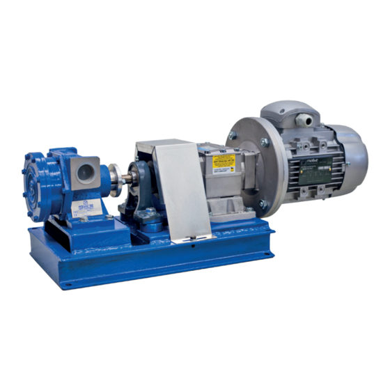
- Page 1 ® INSTRUCTION & MAINTENANCE MANUAL M Series ®...
- Page 3 UNI EN 809:2009; UNI EN 953:2009 3P Prinz S.r.l. hereby declares, under its sole responsibility, that the above-mentioned pump is in conformity with the provisions of the Machinery Directive, as an incomplete Equipment to be incorporated in another Machinery (Directive 2006/42/CE).
- Page 4 UNI EN 953:2009 - Marking: 3P Prinz S.r.l. hereby declares, under its sole responsibility, that the above-mentioned electric pump is in conformity with the provisions of the Machinery Directive (Directive 2006/42/CE). The above-mentioned electric pump has undergone a risk evaluation as per Directive 2006/42/CE, designed and tested in accordance with the above-mentioned Standards.
- Page 5 UNI EN 13463-1:2009; UNI EN 13463-5:2011, UNI EN 13463-8:2004 3P Prinz S.r.l. in addition declares that the above-mentioned pump is in conformity with the provisions of the Machinery Directive, as an incomplete equipment to be incorporated in another machine (Directive 2006/42/ CE).
- Page 6 UNI EN ISO 13732-1:2009 UNI EN 809:2009; UNI EN 953:2009 3P Prinz S.r.l. hereby declares, under its sole responsibility, that the above-mentioned electric pump is in conformity with the provisions of the Machinery Directive (Directive 2006/42/CE). DIRECTIVE 94/9/CE (ATEX) - Applicable Standards:...
-
Page 7: Table Of Contents
TABLE OF CONTENTS CAP.1 PREFACE ..........................6 1.1 Introduction ............................6 1.2 Warranty ............................... 8 CAP.2 CARRIAGE, PACKAGING AND HANDLING ................9 2.1 Carriage and packaging ........................9 2.2 Handling .............................. 10 CAP.3 INSTALLATION ......................... 11 3.1 General installation regulations ....................11 CAP.4 SAFETY ........................... -
Page 8: Cap.1 Preface
CH.1 PREFACE 1.1 INTRODUCTION 3P Prinz S.r.l. thanks you very much for choosing a 3P volumetric pump; please also be advised that all pumps manufactured by the company are produced while taking into account the most advanced technologies and selecting the most appropriate materials. - Page 9 The typical nameplate of the pump is mounted on the pump itself and shows: - The serial number: this number shall always be given to 3P Prinz in case of request for information, spare parts or interventions or in case of claims;...
-
Page 10: Warranty
The warranty expires if the machinery is opened for maintenance, inspection, or attempt of repair of the same, by not qualified personnel (not recognized by 3P Prinz) unless in front of 3P Prinz technical personnel. -
Page 11: Cap.2 Carriage, Packaging And Handling
® CH. 2 CARRIAGE, PACKAGING AND HANDLING 2.1 CARRIAGE AND PACKAGING The carriage and shipment of the pump takes place by truck for both domestic and international shipments. Based on the type and dimension of the components to be shipped and on the destination, 3P Prinz S.r.l. -
Page 12: Handling
® 2.2 HANDLING Packages of large dimensions can be handled by fork-lift truck (see figure 2.4), while small packages, generally not exceeding 25 Kg approximately, can be handled manually (see figure 2.5). ®... -
Page 13: Cap.3 Installation
® CH. 3 INSTALLATION 3.1 GENERAL INSTALLATION REGULATIONS Generally the Pompe 3P® “M” series pumps are supplied complete with motor reduction gear or motor variator and mounted on a suitable base plate; in this case, it is sufficient to fix the group assembly with anchor bolts. - Page 14 ® 6) Place the pump as close as possible to the suction point. 7) The Pompe 3P pumps automatically self-prime in any installation position and do not therefore require foot valves, unless volatile liquids are to be pumped. In this case, the valves must have a passage that is at least equal to the inside diameter of the suction pipe.
-
Page 15: Cap.4 Safety
® CH. 4 SAFETY DEVICES 4.1 GENERAL SAFETY REGULATIONS For a correct use of the pump, the following rules must be complied with: - Please read and follow the instruction, installation, use and maintenance manual supplied with the pump. - Read and follow all the instructions and warnings provided. - The pump must be stopped, while warning those concerned, in the event of defects or anomalous performance (e.g. -
Page 16: Information On The Risks That Cannot Be Eliminated By The Measures Taken By The Designer
® The use of pumps without the envisaged protections is prohibited. Tampering of the safety devices and pump protection devices is prohibited. 4.2 INFORMATION ON THE RISKS THAT CANNOT BE ELIMINATED BY THE MEASURES TAKEN BY THE DESIGNER Mechanical risks can occur on the pump due to impacts or sliding. Risks associated with micro-leaks due to the packing rings. -
Page 17: Cap.5 Noise Level
® CH. 5 NOISE LEVEL 5.1 NOISE LEVEL The noise level in an environment with several pumps can be very high. The following security measures should be applied on the basis of the sound pressure level: - less than 70 dB (A): no protection is necessary. - greater than 70 dB (A) : people who stay in the room must protect their ears - greater than 85 dB (A) : environment with a dangerous level of noise level. -
Page 18: Cap.6 Description Of The Pumps
® CH.6 DESCRIPTION OF THE PUMPS 6.1 VOLUMETRIC PUMPS “M” SERIES (single body) The design of these pumps is suitable to the transportation of fluids with medium, high and very high viscosity, also containing solids in suspension. MATERIALS: A= Body and Cover in Cast Iron, Impeller and Axis in Carbon Steel B= Body and Cover in Cast Iron, Impeller and Axis in Stainless Steel C= Body and Cover in Bronze, Impeller and Axis in Stainless Steel D= Body and Cover in Nickel Plated Cast Iron, Impeller in Nickel Plated Carbon Steel and Axis in... -
Page 19: Working Principle Of The Hollow Disk Pump
® CH.6 DESCRIPTION OF THE PUMPS 6.2 WORKING PRINCIPLE OF THE HOLLOW DISK PUMP In Figure 6.2, the dashed area represents the suction liquid, while the blank area represents the liquid to be pushed, or othwerise the volume to be filled during the suction (depending on the rotation direction). -
Page 20: Cap.7 Usage Of The Pump
® CH. 7 PUMP OPERATION 7.1 OPERATING INSTRUCTIONS FOR POMPE 3P® “M” SERIES PUMPS Before start-up, please ensure that no valves are closed and that there are no blocked or occluded pipes in the system. - Check the direction of pump rotation (see figure 7.1 and 7.2). - Since the pump is reversible, in order to reverse the flow direction in the piping it is sufficient to reverse the rotation direction of the pump. - Page 21 ® Adjustment of the pressure relief valve requires intervention on the adjusting screw b, which is located on the suction side as indicated in figure 7.4. The pressure relief valve must be adjusted as follows, depending on the pressure required by the system (Fig.
-
Page 22: Cap.8 Maintenance
3P Prinz s.r.l. is able to perform, on every type of pump, every type of maintenance or revision that is necessary, and to supply all the spare parts. -
Page 23: Cap.9 Accessories
® CH.9 ACCESSORIES 9.1 FILTER In order to prevent foreign bodies from being sucked by the pump, it is recommended that it will be equipped with a filter to be applied to the suction inlet (see figure 9.1 ). The filter must be periodically cleaned. Cleaning is carried out as follows: - unscrew the bolts (a) and remove the cover (b);... -
Page 24: Pressure Relief Valve
® 9.3 PRESSURE RELIEF VALVE As previously mentioned, the pumps can be equipped with pressure relief valve (temporary by- pass). This accessory protects the pump from the risk of operating with a closed supply pipe. 1. BODY 2. THREADED CAP 3. -
Page 25: Cap.10 Troubleshooting
® CH. 10 TROUBLESHOOTING 10.1 CAUSES OF MALFUNCTION The pumps will provide customer an outstanding performance if installed and used correctly. Please refer to the below notes in the event of operating faults or anomalies. 10.1.1 LACK OF SUCTION - Inlet of intake air - Air or gas bubbles in the liquid - Improperly adjusted stuffing box (that allows inlet of air) - Excessive suction lift... -
Page 26: Zero Flow Rate
® - Pressure relief valve set too low or with possible foreign bodies therein - Delivery pipe closed or partially blocked - Delivery pressure higher than envisaged and consequent opening of the pressure relief valve - Worn-out pump 10.1.3 ZERO FLOW RATE - Pump rotating in wrong direction - Excessive suction lift - Inlet of intake air... -
Page 27: Noise And Vibrations
® 10.1.5 NOISE AND VIBRATIONS - Pipes not secured - Rotational speed too high - Air or gas inside the pump or the system (expel through the appropriate vent cap on the pump) - Suction difficulty due to excessive viscosity of the liquid - Cavitation due to excessive suction lift - Vapour pressure too high - Suction pipes, valves, fittings or connections are on inadequate size (too small) -
Page 28: Cap.11 Decommissioning
® CAP. 11 DECOMMISSIONING 11.1 PUMP DECOMMISSIONING In our pumps, there are no particular materials that require special disposal procedures or special handling. ®... -
Page 29: Cap.12 Spare Parts
® CAP. 12 SPARE PARTS 12.1 SPARE PARTS FOR “M” SERIES (single-body) PUMPS Use figure 12.1, 12.2, 12.3, 12.4 to request the spare parts, while specifying the serial number of the pump, the part number and the type of seal. 12.1.1 EXPLODED VIEW FOR “M”... -
Page 30: Exploded View For "M" Series Pumps (Internal Mechanical Seal)
® 12.1.2 EXPLODED VIEW FOR “M” SERIES PUMPS (internal mechanical seal) 1. BASE 21. COUNTER-FLANGE 2. BODY 22. COUNTER-FLANGE GASKET 3. COVER 24. FRONT BEARING 4. IMPELLER 25. REAR BEARING 5. SHAFT 26. KEY 6. SHAFT HEAD BUSHING 27. CIRCLIP 7. -
Page 31: Exploded View For "M" Series Pumps (External Mechanical Seal)
® 12.1.3 EXPLODED VIEW FOR “M” SERIES PUMPS (external mechanical seal) 1. BASE 19. PLATE GASKET 2. BODY 20. PLATE 3. COVER 21. COUNTER-FLANGE 4. IMPELLER 22. COUNTER-FLANGE GASKET 5. SHAFT 23. PIN 6. SHAFT HEAD BUSHING 26. CIRCLIP 7. MECHANICAL SEAL 28. -
Page 32: Exploded View For "M" Series Pumps (Packing Type Seal)
® 12.1.4 EXPLODED VIEW FOR “M” SERIES PUMPS (Packing type seal) 1. BASE 20. PLATE 2. BODY 21. COUNTER-FLANGE 3. COVER 22. COUNTER-FLANGE GASKET 4. IMPELLER 23. GLAND 5. SHAFT 26. CIRCLIP 6. SHAFT HEAD BUSHING 28. THREADED PLUG 9. PACKING SEAL 30. - Page 34 ® PPrinz ® Tuscany. Italy sales@3pprinz.com www.3pprinz.com ® Pompe 3P and Pera-Prinz are trademarks of 3P Prinz ® ® ® srl...
Need help?
Do you have a question about the Pompe 3P M Series and is the answer not in the manual?
Questions and answers