
Summary of Contents for AW-Lake AW Gear Meters MX 9000
- Page 1 C O M PA N Y MX 9000 Process Monitor Installation, Operating & Maintenance Manual ©2016 AW-Lake Company. All rights reserved. Doc ID:MXMAN082416...
-
Page 2: Table Of Contents
Table of Contents Unpacking ....................3 Quick Guide ...................3 Connect to Sensor .................3 Connect to Power ..................3 Basic Key Definitions ................3 Technical Specifications ................4 Power Requirement ................4 Analog Output 4-20mA................4 Frequency Inputs ...................4 Integrated Linearization ................4 Programming and Data Entry ..............4 Product Description ................5 Principle of Operation ................5 Features ....................5... - Page 3 Min Flow Rate ..................26 Min Flow mA ...................26 Max Flow Rate ..................26 Max Flow mA ..................26 Zero Flow mA ..................26 TOTAL Source ..................26 Zero Total mA ..................27 Max Total Value ..................27 Max Total mA ..................27 GRAND TOTAL source ................27 Zero Grand Total mA ................27 Max Grand Total Value ................27 Max Total mA ..................28 LIMIT/ Pulse Output programming ............28...
-
Page 4: Unpacking
Unpacking Separate the MX 9000 Flow Monitor from packaging materials and check for any visual signs of damage. If you determine there are damages caused by shipping, file a claim with the shipping company. If the flow monitor appears to have been improperly assembled or does not operate properly, return it for replacement or repair (see Limited Warranty information at the end of this manual). -
Page 5: Technical Specifications
Use the SELECT key to move the cursor to the digit you would like to change or reset the total values, use the UP and DOWN keys to change between screens or increase or decrease the value as desired, and use the ENTER key to enter the information. -
Page 6: Product Description
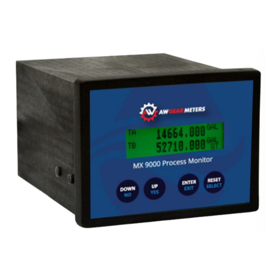
Product Description The MX 9000 Flow Monitor is a versatile, multi-functional device that helps you track rate, flow, limit, ratio, and other variables. The unit’s multicolor back-lighted LCD display is easy-to-read with up to 22 different display modes available, depending on model. The standard unit is one channel, but the optional two- channel version allows you to monitor dual flows and display them in a number of ways: separately, as a sum (for example in total material use), as a difference (as in fuel consumption), or as a ratio of product A/product B. - Page 7 Model Number Key MX9 - X Communication protocol No additional options Options boards 4-20mA output 2, Frequency out, Analog in, 2 relay out 120/240VAC supply, 4-20mA out, Frequency out, 2 relay out Only for batch controller No option board Output options 4-20mA output 1 No outputs Main board options...
-
Page 8: Relay Contact Ratings
Relay Contact Ratings Maximum Switched Resistive Load DC: 60W Power AC: 125VA Inductive Load DC: 30W AC: 60VA Maximum Switched Voltage 100 VDC, 250VAC Maximum Switched Current 2A/DC, 1A/AC Rated Load Resistive Load DC: 30V, 2A Inductive Load AC: 125V, 0.3A NOTE: Maximum wire gauge 16 AWG LOWER TERMINAL BLOCK CONNECTIONS: Pin 1:... - Page 9 UPPER TERMINAL BLOCK CONNECTIONS (Option Board 2): Pin 1: Limit 2 Relay NC Pin 2: Limit 2 Relay NO Pin 3: Limit 2 Relay COM Pin 4: Limit 1 Relay NC Pin 5: Limit 1 Relay NO Pin 6: Limit 1 Relay COM Pin 7: (+) mA Loop 2 Output Pin 8:...
-
Page 10: Sensor / Pulse Inputs
Sensor / Pulse Inputs Pulse inputs are opto isolated and come referenced to signal ground. Regulated +15 VDC at 50mA max is available for powering each sensor. Inputs can also be isolated from the control power by cutting CT1 or CT2 with a sharp knife but then the internal +15 VDC supply is not available. -
Page 11: Analog Output(S)
Analog Output(s) The isolated 16-bit 4-20mA output(s) can be wired for use with Loop powered inputs or for ground referenced inputs. The analog signal has an internal LED in series which varies in intensity as the mA signal varies. This can be used for troubleshooting purposes. -
Page 12: Analog Input (Option Board 1)
Figure 6: Relay Outputs Analog Input (option board 1) The analog input is available on option board 1. It can be configured for either a 4-20 mA input or a 0-5 or 0-10 VDC input. The input is referenced to the system common. -
Page 13: Batch Controller Inputs (Option Board 3)
Figure 8: 120/240 VAC Input Batch Controller Inputs (option board 3) Five inputs are available for remote control of the batch process. You must have ordered the batch model to access these inputs (MX9-B). A 15 VDC output is provided as a supply for the inputs. Program / Run uses a maintained contact (switch), and the other inputs require momentary signals. -
Page 14: Run Mode Screens
Run Mode Screens The run mode screens, as shown below, can be accessed by using the UP and DN buttons. Info screen shows critical information on MX 9000 model number, serial number and firmware version NOTICE: Please have this information available when calling for technical support. RATE screen A shows active flow rate information in programmed engineering units RATE screen B shows active flow rate information in programmed engineering units TOTAL screen A shows totalized volume in programmed engineering units... -
Page 15: Rate Screens
LOGO Screen MX 9000 S/N 0000000 Software Version 1.0.0 HART SW Version 1.0.0 The LOGO screen shows 3 or 4 lines of important data for the display unit which is needed if contacting the factory for support issues. 1. Line 1 shows the basic model name 2. -
Page 16: Status Screen
The TOTAL screen displays the flow total of A or B in programmed engineering units. Pressing the RESET button resets the value back to zero (0). The Total can also be reset remotely by connecting a momentary voltage to the external RESET input. -
Page 17: Ratio A/B (B/A) Screens
You can also access screen control programming from this screen by pushing and holding the ENTER button for 3 seconds. Use the UP – DOWN – SELECT buttons to enter the password code of “53126”. This password cannot be changed. See the advanced programming section for further information on this process. -
Page 18: Analog Out Screen
ANALOG OUT Screen ANALOG OUT RA 04.00 MA ANALOG OUT screen shows the mA value the MX 9000 is outputting. The 2 letters in the upper right corner indicate what variable the mA output has been assigned to represent. 1. FX = Fixed mA output 2. -
Page 19: Ra/Rb Screen
4. Grand Total - The Limit output will change when the GRAND TOTAL reaches the programmed value The second line of each limit represents the actual state of the output pin(s) RA/RB Screen RA 34.00 GPM RB 56.00 GPM The rate A and B screen is another dual combination screen that provides visibility to both rates at the same time. -
Page 20: Rate A + B Screen
RATE A + B Screen RATE A + B 600.00 GPM The rate A + B screen shows the mathematical sum of the two flows of dual channel units. If the gate time or linearizer are active those will also be indicated by a LN in the lower left or GT in the lower right of the display. -
Page 21: Batch Total Screen
The total A - B screen shows the mathematical difference of the two totals of dual channel units. For A total being greater than B, a plus (+) sign will be displayed. If total B is greater than A, a minus (-) sign will be displayed. Pushing the ENTER key will change to the grand total screen. -
Page 22: Programming
Programming Entering programming mode The MX 9000 main programming menus can be accessed from 3 of the run mode screens; [RATE], [ANALOG OUT] and limit [L1/L2] screens. To enter the programming menu from these screens, press and hold the ENTER button for 3 seconds until one of the programming screens appears. -
Page 23: Rate, Total And Grand Total Scaling
If a value has a decimal point whose position can be changed, press the SELECT button until the underscore is under the decimal point. Press the DOWN button to move the decimal point to the left and press the UP button to move the decimal point to the right. -
Page 24: Rate Time Base
The available units are: (US gallons) (Liters) (Cubic centimeters) (Barrels) (Milliliters) (Cubic meters) (Liquid ounces) (Pulses) Once the desired unit is showing, press ENTER to continue. RATE time base Use the UP or DOWN buttons to select the time base to use in conjunction with the previously selected RATE units to define the flow rate unit. - Page 25 The Rate and Total units do not have to be the same. Once the desired unit is showing, pressing ENTER completes the scaling programming for channel A. Repeat the above to program channel B. When done, you will be at the Analog programming menu.
-
Page 26: Fixed Output Source
When entering the Analog programming menu, the first screen asks to select the Analog Source, or what the analog output value is to represent. There are 7 choices: RATE A TOTAL A Grand Total A Rate B TOTAL B Grand Total B Fixed Output Using the UP and DOWN buttons scrolls through the 7 choices that the mA output can represent: a fixed mA output value, input flow rate A or B, the... -
Page 27: Min Flow Rate
RATE source allows the user to configure the mA output to represent the flow rate value. The analog output span can be scaled for either zero to max flow or a non-zero flow to max flow. If the flow rate goes above the programmed maximum flow rate, the analog output will continue to increase, up to a maximum of 22mA. -
Page 28: Zero Total Ma
Figure 15: Total Source Zero Total mA Enter the mA value to represent a zero totalizer value. Minimum allowable value is 2mA. Max Total Value Enter the maximum totalizer value to monitor. Max Total mA Enter the mA to represent the above entered maximum totalizer value. 20mA is the maximum allowable value. -
Page 29: Max Total Ma
Max Total mA Enter the mA to represent the above entered maximum totalizer value. 20mA is the maximum allowable value. LIMIT/ Pulse Output programming Figure 17: Limit/Pulse Output Programming Two relay outputs and an opto coupler frequency output are available on option cards 1 and 2. - Page 30 Cycle Output (pulsed output) Figure 18: Cycle Output The CYCLE OUT limit function provides an incremental output signal for a remote totalizer, typically at a lower resolution and frequency. Assigning a limit to the CYCLE OUT function toggles the state of the limit output whenever the TOTAL increments by the programmed cycle amount.
-
Page 31: Rate Value
Each Limit can be set to trigger its output based on a certain flow rate or total set point. This is often used to indicate if a flow rate is outside its intended limits or if a certain total value has been reached in a batch application. Rate Value The limit output will be off if the incoming flow rate is below the programed Rate Value and the output will be on if the incoming flow rate is equal to or above the... -
Page 32: Frequency Output Programming
WARNING / ALARM AB / BA Value The Warning or Alarm AB / BA limit will activate the selected relay when the respective limit is reached in the Ratio AB and BA menus. Select the Warning or Alarm trigger desired and set the values in the Ratio menus starting on page 35. Frequency Output Programming Figure 22. -
Page 33: Linearizer Programming
Linearizer Programming Figure 24. Linearizer Programming The MX 9000 has a 10-point linearizer which can be used to increase the linearity of the flow rate reading. When entering the Linearizer programming mode, the first question asked is if the Linearizer should be activated. If the linearizer has already been programmed, de-activating the linearizer does not erase any previously programmed table values. -
Page 34: Quadrature Signal Programming
To clear a previously programmed linearizer table, enter the linearizer table and change Point 1 Freq. to zero (0). After pressing the ENTER button, the MX 9000 will display a warning that all table values will be cleared. If this is correct, press the YES button. -
Page 35: System Settings Programming
NOTE: Enabling the quadrature signal display will automatically disable all screens associated with channel B as it is required that when using quadrature signals it can only be with one flow meter. System Settings Programming Figure 26. System Settings Programming The system settings menu allows for the customization of the decimal places and background color of the LCD display during limit operation. - Page 36 Before starting the calibration routine, make sure the analog output is connected to the intended readout equipment. To calibrate the MX 9000 it is necessary to enter the analog value read from the user’s readout equipment. Figure 27. Calibrating Analog Output From the run mode STATUS screen, press and hold the ENTER button for 3 seconds to reach the password screen.
-
Page 37: I/O Manual Adjustment
I/O Manual Adjustment Whether for troubleshooting purposes or to manually control external equipment, the MX 9000 allows the user to enter an I/O routine in which the analog output, Limit outputs and Frequency outputs can be controlled and the external Reset input can be monitored. -
Page 38: Fine Ma Adjustment
Fine mA adjustment Figure 29. Fine mA Adjustments When you SELECT the Fine adjustment option, the screen above will appear which shows the active mA output value. Change this number to any desired value between 2.00mA and 20.00mA and when ENTER button is pressed, the MX 9000 will output this value. -
Page 39: Fine Limit Output Adjustment
25Hz increments using the UP and DOWN buttons. The ON/OFF adjustment allows the user to individually toggle the output state between on and off using the SELECT button. Fine Limit Output Adjustment Figure 31. Fine Limit Output Adjustment When choosing the Fine adjustment option, the screen will appear which shows the active frequency output value on the Frequency output. -
Page 40: On/Off Output Adjustment
ON/OFF Output Adjustment Figure 33. On/Off Limit output adjustment ON/OFF Limit output adjustment When choosing the ON/OFF adjustment option, the screen will appear showing the current state of each output. By pressing the UP, DOWN and SELECT buttons, each associated output as shown above will change the state. -
Page 41: Alarm /Ab Alarm B/A
When programming, follow these guidelines: • Program the channel A and B K-Factors, decimal locations, and engineering units from the TOTAL A and TOTAL B displays. See page 22 for details. • Program the parameters for ratio monitoring, including the ratio error limit percentages, from the RATIO screen. -
Page 42: Batch Total Programming
is from 1 to 65534. The recommended typical range for values is from 200 to 2000. Initial value is 500. BATCH TOTAL Programming Use the BATCH TOTAL program mode to quickly dedicate both limits as total limits and program the values at which the limits (labeled S1 and S2) activate. Using the UP and DOWN keys, select the BATCH TOTAL display. -
Page 43: Basic Programming Setup
20 pre-programmed batch quantities. NOTE: The following section only applies to models MX9-B that were shipped programmed as a batch controller. All other units contain only one batch function as shown on page 38. Remote control functions are also only available on the batch controller model. Basic programming setup The basic controller setup is accomplished in an identical manner as a standard MX-9000 monitor for such things as K-Factor, analog output, gate time and... -
Page 44: Delay
DELAY This variable sets the delay time for Limit 1 relay (high flow solenoid output) relative to the START input. Typical delays are from 0.00 to 4.00 seconds. This function is used in slow start applications where Limit 2 relay (low flow solenoid output) is energized immediately at a START input and Limit 1 relay (high flow solenoid output) is turned on after the DELAY time. -
Page 45: Operation
OPERATION To run a batch, select one of the pre-programmed ones using the batch select switch, then press the start / stop switch. Note that any of the 20 presets that are programmed with 0 for both limits will be skipped. Immediately the low flow output (relay 2) will energize and the display will indicate “RUN”. - Page 46 ENTER. The “CLEAN SWEEP” screen will appear. This function can take up to 45 seconds to complete – DO NOT TURN OFF OR INTERRUPT POWER DURING THIS OPERATION! WARNING: Performing a “CLEAN SWEEP” operation will erase ALL programmed information including K-factors, linearizer tables and output limits programming.
-
Page 47: Appendix A - Physical Dimensions
Appendix A - Physical Dimensions 3.8” / 97mm 2.8” / 72mm MX 9000 Process Monitor 5.5” / 139mm 5.2” / 132mm Option board 2.58” / 65mm Main board... - Page 48 Back panel configuration will vary by model. See pages 10-12 for terminal block connections. Also refer to decal on terminal block for signal identification.
-
Page 49: Appendix B - Default Variable Values
Appendix B – Default Variable Values Analog output 2mA (Fixed) Frequency output Gate Time 1.0 Seconds GRAND TOTAL units GAL (always same as TOTAL units) K-factor Limit 1 Limit 2 Linearizer RATE unit RATE time base Minutes TOTAL... -
Page 51: Limited Warranty
Limited Warranty AW-Lake Company warrants the product to be in good working order for a period of 1 (one) year from the date of purchase from AW-Lake Company or an Authorized AW-Lake Company distributor. Should the product fail to be good... - Page 52 C O M PA N Y 414.574.4300 | www.aw-lake.com 2440 W. Corporate Preserve Dr. Oak Creek, WI 53154 ©2016 AW-Lake Company. All rights reserved. Doc ID:MXMAN082416...
Need help?
Do you have a question about the AW Gear Meters MX 9000 and is the answer not in the manual?
Questions and answers