
Subscribe to Our Youtube Channel
Related Manuals for Electro Cam Plus PS-6144 Series


Summary of Contents for Electro Cam Plus PS-6144 Series
- Page 1 PLµS PS-6144 Series ® Programmable Limit Switch 6000 Series Programming & Installation Manual Metric Rd • Roscoe, • • • 13647 IL 61073 USA 815/389-2620 FAX 815/389-3304 800-228-5487 (U.S.A. and Canada)
- Page 2 Copyright © 2001 All Rights Reserved Neither this document nor any part may be reproduced or transmitted in any form or by any means without permission in writing from the publisher. , SLIMLINE ® , PLµS ® , and PLµSNET are all registered trademarks of ®...
-
Page 5: Table Of Contents
Analog Output ......3-4 PLuSNET II Program ....6-1 Analog Quantity ......3-5 Serial Communications Using Channel Copy ......3-6 Electro Cam Corp. Protocol .... 6-3 Communications ......3-6 Default Program ......3-7 Error Codes ........6-12 Enable Codes ......3-8 Checksum Calculations .... - Page 6 WARRANTY 1. Electro Cam Corp. warrants that for a period of twelve (12) months from the date of shipment to the original purchaser, its new product to be free from defects in material and workmanship and that the product conforms to applicable drawings and specifications approved by the Manufacturer.
-
Page 7: Section 1-Introduction
Mechanical Cam Switches Mechanical Cams The PS-6144 Programmable Limit Switch electronically simulates mechanical cam switches. A cam switch consists of a roller limit switch whose arm rides on a cam as shown in Figure 1. The cam shaft is driven by a machine at a 1:1 ratio, so that the cam switch turns on and off at specific positions in the machine cycle. -
Page 8: Ps-6144 Description
Programmable Limit Switches PS-6144 Electro Cam Corp. Controller Foot Mount Resolver With Side/Top Connection PS-6000 Series Keypad/Display Figure 2—PS-6144 Programmable Limit Switch and Resolver PS-6144 Description Controller & Keypad PS-6144 Series Programmable Limit Switches consist of two main components, the controller and the keypad/display. -
Page 9: Basic Terminology
Basic Terminology The following terms will be used throughout this manual to explain PS-6144 installation, programming and operation: Channels Each Channel (CHN) in the PS-6144 controller contains “on” and “off” setpoints for one 360° revolution of the resolver shaft. Channels are one of two types: Output Channels—These channels use a switching transistor or an output module to turn an external circuit on or off. -
Page 10: Ps-6144 Optional Features
PS-6144. Serial Communication Using Electro Cam Corp.ʼs PLuSNET software for IBM-PC compatible computers, the controllerʼs entire program can be saved to a disk file or loaded from a disk file to the controller. -
Page 11: Section 2-Installation & Wiring
The controller body mounts on a DIN rail as shown in Figure 4. Keypad/Display Mount the keypad/display to a panel using the four studs on the back of the keyboard. Enclosures are available from Electro Cam if an appropriate mounting location does not exist. DIP Switches For convenience, set the DIP switches on the side of the controller and keypad to their proper positions before mounting the units in a panel. -
Page 12: Mounting Dimensions
Mounting Dimensions Figure 4—Mounting Dimensions 2-2 Installation & Wiring... -
Page 13: Terminals & Components Ps-6144-24M17
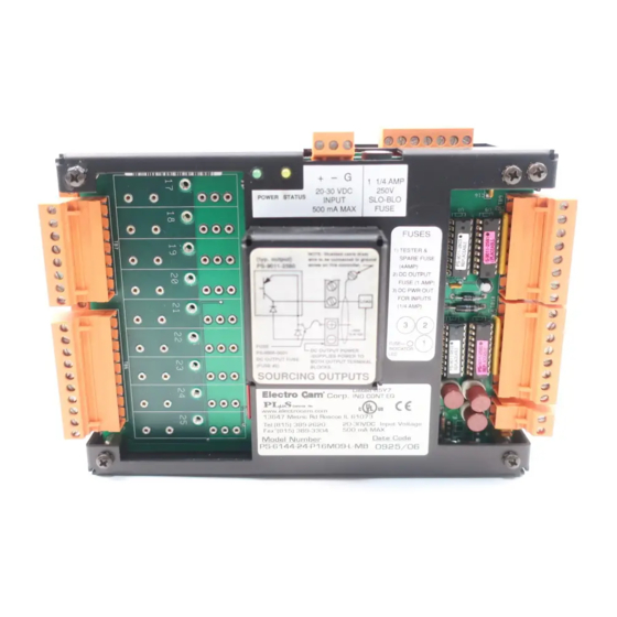
Terminals & Components—PS-6144-24M17 Figure 5—PS-6144-24M17 Terminals & Components Top View Left Side View Yellow Right Side View Front View Terminal Block Details Terminal Block Function ECC Part # TB 1 Inputs #9–16 PS-9006-0024 TB 2 Auxiliary power output PS-9006-0018 TB 3 Inputs #1–8 PS-9006-0023 TB 4... -
Page 14: Ps-6144-24-X16-M09
Terminals/Components PS-6144-24-X16-M09 Figure 6—PS-6144-24-X16-M09 Terminals & Components Left Side View Top View Yellow Right Side View Front View Terminal Block Details Terminal Block Function ECC Part # TB 1 Inputs #9–16 PS-9006-0024 TB 2 Auxiliary power output PS-9006-0018 TB 3 Inputs #1–8 PS-9006-0023 TB 4... -
Page 15: Controller Input Wiring
Controller Input Wiring Input Terminals Hardware inputs can be used to select a program of setpoints or activate groups of outputs based on sensor signals according to mode logic as described in Section 5. The 16 inputs on the PS-6144 are arranged on two terminal strips, TB 1 and TB 3, as shown in Figure 7. - Page 16 Controller Input Wiring (cont’d) Figure 7—Controller Input Wiring (See Figures 5 & 6 for Terminal Block Locations) Sourcing Devices Sinking Devices (+VDC is being switched) (DC common is being switched) Term. Function Program Select Group 1 Input Group 2 Input Group 3 Input Group 4 Input Group 5 Input...
- Page 17 For BCD, calculate the program selected by For Binary, calculate the program selected by Electro Cam 8-position Gray Code selector adding up the values for each of the inputs that adding up the values for each of the inputs that switches are available as accessories for PS- are on.
-
Page 18: Output Wiring
Output Wiring Output Types The outputs available depend on the PS-6144 Model: Output Model Model Type 6144-24M17 6144-24-X16-M09 Transistor None Outputs 1-16 AC/DC/RR Modules Only Outputs 1-15 Outputs 17-23 AC/DC/RR or Analog Modules Outputs 16 & 17 Outputs 24 & 25 The load device to be driven must match the output type. - Page 19 Output Wiring (cont’d) Figure 9—Wiring for Output Modules PS-6144-24M17 PS-6144-24-X16-M09 - - - Electro Cam DC Output AC Output Sourcing Sinking Most applications will not need the varistor or R-C suppressor shown above. However, when other switching devices are in series or parallel with the AC module, voltage spikes may damage the module.
- Page 20 Output Wiring (cont’d) Figure 10—Wiring for Sinking Transistor Outputs (See Figure 6 for Terminal Block Locations) Model PS-6144-24-N16-M09 Please Note: • Outputs are rated at 30 VDC, 50 mA. • Transistor outputs should not be used to switch inductive devices such as solenoids or relays. •...
- Page 21 +DC voltage to the connected device. This information is important when interfacing an Electro Cam Corp. product with another electronic device. If you are using an Electro Cam Corp. product input to an Allen-Bradley 1746-IN16 “sinking” input card* or similar A-B device, you have to supply a +DC voltage (Electro Cam Corp. Sourcing output) to this card, NOT a DC common or ground.
-
Page 22: Keypad Wiring
Keypad Wiring Number of Keypads One or two keypads may be connected to a PS-6144 controller as shown in Figure 12. See Figure 14 for possible system configurations. Programming Enable The wiring connector on the back of each keypad includes terminals to select Operator or Master level programming for that keypad. -
Page 23: Dip Switch Configurations
DIP Switch Configurations DIP Switches Each keypad and controller has a DIP switch as shown in Figure 13. For convenience, set the DIP switches correctly before mounting the units in a panel. Keypad Settings The address and termination settings on the keypad DIP switch apply to the RS-485 network that connects it to the controller. - Page 24 DIP Switch Configurations (cont’d) Figure 14—DIP Switch Settings for Typical Systems One Keypad Two Keypads, Controller on End Two Keypads, Controller in Middle DIP Switch Guidelines Termination: • Termination must be “on” for devices on each end of the chain. •...
-
Page 25: Communications Wiring
Communications Wiring DB-9F Port Serial communication to a PLC or other system host is provided through a DB-9 female connector as shown in Figures 5 & 6. This connector can be wired for RS-232 or RS-485 communications. RS-485 RS-485 can be used for “multi-drop” networks where more than one controller could be connected to the system host. -
Page 26: Resolver Installation
For these reasons, it is recommended that customers do not make their own resolver cables. Electro Cam will make resolver cables any length up to 1000' and can expedite shipment as required. -
Page 27: Resolver Dimensions
Resolver Dimensions Figure 16 - Electro Cam Corp. Resolvers Foot Mount 0.749/ 0.747" 19.02/ 18.97 mm With Rear Connector (shown): PS-5275-11-ADR With Side Connector: PS-5275-11-ADS Cable: PS-5300-01-XXX where “XXX” is length in feet. Flange Mount 0.375/ 0.374" 9.53/ 9.50 mm... -
Page 28: Resolver Cables
In some installations, it may be advisable to disconnect the lug to prevent ground loops through the cable shield. Consult Electro Cam if electrical noise problems are suspected. -
Page 29: Fuse Tester & Fuse Replacement
Fuse Tester & Fuse Replacement Fuse Tester Figure 17 shows the location of a fuse test socket and LED which can be used to test TR5 style fuses. PS-6144 controllers are shipped with a spare 4A fuse mounted in the test socket. -
Page 30: Output Transistor Replacement
Output Transistor Replacement Check Fuse First If all of the transistor outputs fail to work, check the 1A fuse shown in Figures 17 & 18. Also check to be sure that a 10–30 VDC power supply is connected to TB 11, Figure 6. Correct Problems Chips will most likely be damaged by one of two events: •... -
Page 31: Keypad Overview
Keypad Overview Figure 19—Keypad Keys and Corresponding Functions Main Screen • Shows Active Program, RPM, Position, and Group # if applicable. • See MAIN SCREEN in this Section for details. • Press SEL key when cursor is on “MENU” to enter Menu Tree (Fig. -
Page 32: Menu Tree
Menu Tree Figure 20—PS-6144 Menu Tree • Functions are listed alphabetically in Section 3 of this manual starting on page 3-4. ESC SEL MAIN SCREEN PASSWORD SETPOINTS DEFAULT PROGRAM SETUP MENU SPEED COMP ESC SEL TIMED OUTPUTS OFFSET MOTION DETECTION ANALOG OUTPUT PULSE COPY CHN COPY... -
Page 33: Initial Programming
Initial Programming Bench Test To test the PS-6144 prior to installing it, do the following: 1. Plug output modules into the controller beginning with Position 1 on the PS-6144- 24M17, or Position 17 on the 6144-25. See Figure 9. 2. Connect a resolver. See Figure 16. 3. -
Page 34: Analog Output
Analog Output Menu Path MAIN SCREEN to SETUP MENU to ANALOG OUTPUT Purpose Analog output signals are linearly proportional to the resolver RPM. Two types of analog output modules are available: 0-10 VDC and 4-20 mA. This function assigns Offset and High RPM values to output positions for analog mod- ules. -
Page 35: Analog Quantity
Analog Output (Contʼd) Offset Analog Offset is the analog signal level that will be output when the resolver is at zero RPM. This allows the minimum analog signal to be greater than zero volts or 4 mA. Because the analog output module has 4096 increments (12 bits) of signal level avail- able, the offset is specified as the number of increments of signal that should be output at zero RPM. - Page 36 Channel Copy Menu Path MAIN SCREEN to SETUP MENU to CHN COPY Purpose Channel Copy allows you to copy all setpoints to another channel in the specified pro- gram. Screens The Channel Copy function consists of four screens: Program containing channels SOURCE PGM:---< Program containing channel DEST PGM:---< to be copied Channel to be copied SOURCE CHN:---< Destination channel to be copied to DST CHN:---<...
-
Page 37: Default Program
Communications (Contʼd) Baud Rate Use SEL to toggle between the available baud rates. The baud rate must match that of the host computer. Available baud rates are: 4 ,800; 9,600; 19,200; and 38,400. Note: Effective with Software Versions 1.97 and higher, the communications screen has been revised as shown below: TYPE: 232 ADR:1< TRM: ON BR: 9600 Termnination Setting The termination setting should be ON if TYPE is set to RS-232, or if TYPE is set to RS-485 and only one PS-6144 controller is in the multi-drop network. Setting the termination to OFF in these configurations may cause inaccurate RPM readings. -
Page 38: Enable Codes
Enable Codes Menu Path MAIN SCREEN to CONFIG MENU to PGM ENABLE MENU to ENABLE CODES Background The PS-6144 has three levels of programming access: Operator, Setup, and Master in order of increasing capabilities. Figure 21 lists the menu functions that can be pro- grammed under the various levels of access. Programming levels can be activated, or “enabled,”... - Page 39 Enable Codes (contʼd) Figure 21—Programming Access Programming Level Levels for Various Menu Items Normal Display Operator Setup Master Can Be Enabled By… Keypad Terminal --- Yes (E2) Yes (E1) Password --- Yes Yes Menu Item Access Password Enter Enter Enter Program Setpoints View Program Program Program...
-
Page 40: Enable Options
Enable Options Menu Path MAIN SCREEN to CONFIG MENU to PGM ENABLE MENU to ENABLE OPTIONS Purpose The Enable Options screen controls Operator Level access to SETUP MENU program- ming as indicated in Figure 21, note 1. Screen SETPOINTS or SETUP MENU screen. Scroll through choices with UP and Down cursor keys. SETPOINTS< ENABLE: ON OPERATOR ENABLE: ON/OFF (Toggle with SEL key) This screen lists the various items in the SETUP MENU, and allows you to turn Operator access to those items on or off. -
Page 41: Increasing Direction
Group Position Display (Contʼd) The value selected in this screen determines the appearance of the main screen as shown below: Main Screen— • One Output Group, and GRP POS DISP Set to “One” or “Each” • Multiple Output Groups, and GRP POS DISP set to “One” Active Program Machine Speed PGM: 1 RPM: 1500... -
Page 42: Input Status
Input Status Menu Path MAIN SCREEN to SETUP MENU to I/O STATUS to INPUT STATUS The input status screen displays the On/Off status of the DC inputs on Terminal Blocks TB 1 and TB 3, Figure 7. Screens 12345678 INPUT Input Numbers (1-8) 01001001 1-8< Input On/Off Status (0=Off, 1=On) 90123456 INPUT Input Numbers (9-16) -
Page 43: Main Screen
Main Screen Two Screens On power-up, or after five minutes of keypad inactivity, the controller will display one of two main screens: Main Screen— • One Output Group, and GRP POS DISP Set to “One” or “Each” • Multiple Output Groups, and GRP POS DISP set to “One” Active Program Machine Speed PGM: 1 RPM: 1500 Machine Position = Shaft Position + Offset MENU<... -
Page 44: Memory Tests
Memory Tests Menu Path MAIN SCREEN to TEST MENU to MEMORY TESTS Purpose This menu selection provides three functions that allow you to clear programmed values from the controller. An additional function tests the controllerʼs watchdog timer. Screen MEMORY TESTS Enter function here FCN:----< Programming To perform one of the memory test functions, enter the function number using the nu- meric keys and press SEL. -
Page 45: Motion Detection
Motion ANDing (Contʼd) Programming Select a new channel by pressing the INC/DEC keys, or through direct numeric entry followed by ENT. Press the SEL key to toggle the ANDing to L1, L2, or OFF. Operation • Any number of output channels can be ANDed to a single Motion Detection level. • Motion ANDing and Output Enable ANDing can be combined for any given output channel. • When Motion ANDing is activated for a channel, it will apply to that channel in all programs. Motion Detector An output channel can be used as a motion detector by programming it to be on at “1” and off at “1,” and then ANDing it with the desired Motion Level. This will turn the output on constantly as long as the machine speed is within the specified Motion Level range. See Also MOTION DETECTION Motion Detection Menu Path... -
Page 46: Offset
Offset Menu Path MAIN SCREEN to SETUP MENU to OFFSET Background Because the PS-6144 is a programmable device, it can be set to display a position of “zero” at any point in the machine cycle. Usually, a machine is jogged to the beginning of a cycle, and the SHAFT POSITION function is set to zero at this point. In addition, each output group operating in Mode 0, 3, 4, or 5 can be individually “offset”... - Page 47 Offset (contʼd) Offset Programming To change the offset for an output group in Mode 0, 3, 4, or 5, first select the group by moving the cursor to GRP. Use INC or DEC, or the numeric keypad and ENT to select the group. Offset can be programmed in two ways: Direct Entry—Enter the offset directly by moving the cursor to ABS and entering the offset value on the numeric keypad, followed by ENT. Group Position—Jog the machine to a position that corresponds to the desired group position, move the cursor to POS, and enter the group position using the numeric key- pad, followed by ENT. For example, jog the machine to a point where the group position should be zero, then press “0” ENT while the cursor is at POS.
-
Page 48: Output Enable Anding
Output Enable ANDing Menu Path MAIN SCREEN to CONFIG MENU to CHN ANDING MENU OUTPUT ENABLE ANDING Purpose Output Enable ANDing allows you to AND any output channels with Input Terminal #16, Figure 7. A channel ANDed with this terminal will be enabled to turn on at its programmed setpoints only while the terminal is energized. -
Page 49: Output Status
Output Groups (Contʼd) Grouping Example 3—Three Groups Output Includes Group Outputs Mode 1 & 2 3 & 4 5 thru 25 Programming Begin by moving the cursor to GRP QTY and entering the number of groups desired, followed by ENT. Next, move the cursor to GRP and enter “1”... -
Page 50: Password
Output Status (Contʼd) Selecting Outputs Press the SEL key to change the set of outputs displayed. Forcing Outputs Forcing outputs allows you to force an output on or off for diagnostic purposes. This function is not available on earlier software models. Note: When leaving the Output Status screen, keep in mind that any outputs that have been forced will return to their originally programmed state. -
Page 51: Per Channel Enable
Password (Contʼd) Clearing a Password When programming operations are completed, enter a password value of “0,” then ENT to clear the enable level. If a keypad is left unattended with an active password, the access code will clear after five minutes of keypad inactivity and the keypad will revert to the “Normal Display” mode shown in Figure 21. -
Page 52: Program Select Mode
Program Select Mode Menu Path MAIN SCREEN to CONFIG MENU HARDWARE to PGM SEL MODE Purpose This screen allows you to specify the format for the hardware Program Select inputs on Terminals 1 through 8 of Terminal Block 3, Figure 7. Screen Hardware Program Select Format: BIN = Binary, GRAY = Gray Code, BCD = Binary Coded Decimal... - Page 53 Pulse Copy (contʼd) Example Generate a train of pulses as follows: Pulse Each pulse is 50 increments wide, separated from the next pulse by 50 increments. Program PULSE COPY as follows: Program to add pulses to; PROGRAM:---< Enter number, then SEL to go to next screen Channel to add pulses to;...
-
Page 54: Rate Setup
Rate Setup Menu Path MAIN SCREEN to CONFIG MENU to DISPLAY RATE SETUP Purpose The Rate Setup function allows you to configure the RPM display on the Main Screen. Three parameters can be programmed: • Units—The Main Screen can label the resolver speed as Revolutions Per Minute (RPM), Bags Per Minute (BPM), Cartons Per Minute (CPM), or Inches Per Minute (IPM). -
Page 55: Resolver Type
RESOLVER TYPE Purpose The PS-6144 can operate with resolvers that have a transformation ratio of .454 or 1. Standard Electro Cam resolvers have a ratio of .454. Some resolvers made by other manufacturers have a ratio of 1. Screen RESOLVER Pressing the SEL key changes resolver type to OTHER. -
Page 56: Setpoint Use
Setpoint Use Menu Path MAIN SCREEN to SETUP MENU to SYSTEM INFO SETPOINT USE Purpose This function displays the total number of setpoint On/Off pairs, or “pulses” available for programming, and the number of pulses that have been programmed. Screen Total number of pulses available for programming TOTAL: 1200 Number of pulses programmed into all channels... - Page 57 Setpoints (Contʼd) • If a channel contains no pulses, the ON and OFF setpoints will be “0.” • If a channel is always on, both the ON and OFF setpoints will be “1.” CH:1 EDG ON and OFF setpoints both 0 if no pulses ON: 0<...
-
Page 58: Shaft Position
Shaft Position Menu Path MAIN SCREEN to CONFIG MENU to HARDWARE MENU to SHAFT POSITION Purpose Because the PS-6144 is a programmable device, it can be set to display a position of “zero” at any point in the machine cycle. Usually, the machine is jogged to the beginning of a cycle, and SHAFT POSITION is set to zero at this point. -
Page 59: Speed Comp Mode
Speed Compensation (contʼd) Speed Comp Units Speed compensation is programmed by entering the response time of the output device in milliseconds (.001 Sec). The output will always turn on this number of msec before the programmed ON position is reached, and turn off this number of msec before the programmed OFF position is reached. -
Page 60: Timed Outputs
Timed Outputs Menu Path MAIN SCREEN to SETUP MENU to TIMED OUTPUT Purpose Any four outputs can be programmed to time out rather than remain on until an OFF setpoint is reached. This makes the output duration constant regardless of machine speed. -
Page 61: Section 4-Speed Compensation
Introduction To Speed Compensation What Is It? “Speed compensation” refers to the ability of the PS-6144 controller to automatically advance or retard setpoints in any output channel depending on the speed of the ma- chine. Speed compensation allows devices with fixed response times, such as glue guns, to perform their functions with high accuracy over a wide range of machine speeds. -
Page 62: Examples
Standard Speed Comp Example Figure 22 illustrates a simple carton gluing application. A conveyor moves cartons under a glue gun which releases glue onto the flaps. The conveyor is connected through a timing chain and sprocket to a transducer which rotates one revolution for each carton that passes under the gun. - Page 63 Standard Speed Comp (Cont’d) Figure 23—Speed Compensation at Various Speeds Setting Speed Comp In many applications, speed compensation can be set by jogging the line to determine ON and OFF setpoints at zero speed, then entering the speed compensation value into the controller.
-
Page 64: Leading/Trailing Speed Comp
Standard Speed Comp (cont’d) Since the new speed compensation value will affect the ON and OFF setpoints already programmed, you will need to start the line one more time and, at a constant speed, adjust the ON and OFF setpoints for proper gluing. Once set, vary the line speed to confirm that the speed compensation value is accurately adjusting the setpoints over the operating speed range. - Page 65 Leading Trailing Speed Comp (Cont’d) Once the second pair of setpoints is established, calculate separate leading and trailing edge speed comp values as shown in Figure 25. Since the new speed compensation value will affect the ON and OFF setpoints already programmed, you will need to start the line one more time and, at a constant speed, adjust the ON and OFF setpoints for proper gluing.
-
Page 66: Negative Speed Comp
Negative Speed Compensation Negative Speed Comp Normal speed compensation advances the setpoints in an output channel to compensate for a fixed response time in the device being controlled. In some applications, however, negative speed compensation is required to retard the setpoints in an output channel. Negative speed compensation is usually found in two situations: “Wrap-Up”... -
Page 67: Section 5-Output Grouping & Modes
Introduction to Groups & Modes nput Signals In many industrial applications, the action of a machine component such as a glue gun, solenoid, or pneumatic cylinder is related to an input signal from a limit switch, sensor, or controller such as a PLC. Input signals are commonly used in two ways: •... -
Page 68: Mode 0
Introduction to Groups & Modes (cont’d) Group Programming PS-6144 output channels are divided into groups through OUTPUT GROUP programming. Each group is automatically associated with one of the input terminals on TB 1, Figure 7, as well as a special “Group Channel” ranging from Channel 91 to 96. The relationship between groups, input terminals, and group channels is summarized in Fig. - Page 69 Mode 0 Operation Description Output channels in a group assigned to Mode 0 function normally and are not affected by the corresponding input terminal or group channel. Details • MOTION ANDING and OUTPUT ENABLE ANDING can be used with outputs in a Mode 0 group.
-
Page 70: Mode 1
Mode 1 Operation (Cont’d) Figure 29—Mode 1 Example Application Three sections of an adjustable phase converting machine are controlled by a single PLuS controller and resolver. Groups 1, 2 and 3 all operate in Mode 1. The position of each group is reset to the “preset” value when the group’s sensor detects the registration mark on the shaft for the corresponding machine section. -
Page 71: Mode 2
Mode 2 Operation (Cont’d) • Either edge of a pulse in the group channel can re-arm the input terminal. If the re- solver shaft is rotating in the forward direction (position is increasing as shaft rotates) the “on” edge of the pulse will re-arm the terminal. If the shaft is rotating in the reverse direction (position decreasing as shaft rotates), the “off”... -
Page 72: Mode 3
Mode 3 Operation (Cont’d) Mode 3 Programming See Figure 28 for input terminal assignments. 1. Program OUTPUT GROUPS to establish groups and modes. 2. Use OFFSET to program the absolute offset value for any Mode 3 groups. 3. Program setpoints into the output channels in the group. Remember that the output channels in Mode 3 will be enabled only while a signal is applied to the group ter- minal. -
Page 73: Mode 4
Mode 4 Operation (Cont’d) Mode 4 Programming See Figure 28 for input terminal and group channel assignments. 1. Program OUTPUT GROUPS to establish groups and modes. 2. Use OFFSET to program the absolute offset value for any Mode 4 groups. 3. -
Page 74: Mode 5
Mode 5 Operation (cont’d) Figure 33—Mode 5 Example Application The glue gun will be enabled for one machine cycle if the sensor sees a carton during the pulse programmed into the group channel. If a carton is missing, the glue gun will not activate. If the line stops, the glue gun will be disabled immediately. - Page 75 To use PLµSNet II, a serial communications cable is required to connect the PLµS controller to an IBM compatible personal computer. This cable can be purchased from Electro Cam Corp., or it can be built by the customer using the wiring information shown in the PLµS Programming and Installation Manual.
- Page 76 PLµSNET II Program (cont’d) Sample ASCII Program Copied from PS-6144 Using PLµSNET II 6-2 Communications...
-
Page 77: Serial Communications Using Electro Cam Corp. Protocol
Serial Communications Using Electro Cam Corp. Protocol (Standard 6144 Units) Background PS-6144 controllers include programming that allows them to accept and respond to a set of serial commands issued by a system host such as a PLC or other computer. The commands can interrogate the PS-6144 for operating and control data, and they can also change programming values within the PS-6144. - Page 78 Serial Commands Description The PS-6144 controller recognizes a set of 95 commands. Some of these commands involve testing and diagnostic functions performed at the factory. Because these commands are of little use in field installations, they are not included in the following pages.
- Page 79 Serial Commands (cont’d) (hex) Name Function Configuration Kbd Qty Number of keypads connected. Commands Put: ! ADR 56 P XX CSM <CR> Reply: A <CR> ! ADR 56 G CSM <CR> Get: Reply: A XX CSM <CR> where “XX” = number of keypads connected. Setup ID Setup ID code.
- Page 80 Serial Commands (cont’d) (hex) Name Function Configuration Inc Direction Direction of increasing rotation. Commands ! ADR 12 P <00 or 01> CSM <CR> Put: (cont’d) Reply: A <CR> Get: ! ADR 12 G CSM <CR> Reply: A <00 or 01> CSM <CR> where “00”...
- Page 81 Serial Commands (cont’d) (hex) Name Function Spd Cmp Mode Standard or Leading/Trailing mode. Configuration Commands ! ADR 1A P <00 or 01> CSM <CR> Put: Reply: A <CR> (cont’d) Get: ! ADR 1A G CSM <CR> Reply: A <00 or 01> CSM <CR> where “00”...
- Page 82 Serial Commands (cont’d) (hex) Name Function Configuration Grp Offset Output group offset value. Commands Put: ! ADR 1E P XX YYYY CSM <CR> (cont’d) Reply: A <CR> ADR 1E G XX CSM <CR> Get: Reply: A YYYY CSM <CR> where “XX” is the group number minus 1. “YYYY” is the offset value for that group, in hex.
- Page 83 Serial Commands (cont’d) (hex) Name Function Spt Count Return number of pulses. Setpoint Commands Cmd: ! ADR 22 CSM <CR> Reply: A XXXX CSM <CR> where “XXXX” is the total number of pulses in hex. Includes all pulses in all channels and programs in the controller. Wipe Spt Deletes all pulses from EEPROM.
- Page 84 Serial Commands (cont’d) (hex) Name Function Setpoint Inc Spt Advances one edge of a pulse, both edges, or all pulses in a Commands channel, by one scale factor increment. (cont’d) ! ADR 28 XX YY ZZZZ TTTT MM CSM <CR> Cmd: Reply: A <CR>...
- Page 85 Serial Commands (cont’d) (hex) Name Function Special Key Press Adds a value to the keyboard buffer; just like pressing a key. Commands ! ADR 2A XX CSM <CR> Cmd: Reply: A <CR> where “XX” is the key number in hex. See “Keypad Diagnostics” in Section 7 for a method to determine the key number for each key on the keypad.
-
Page 86: Error Codes
Error Codes Error Replies If a command sent to the PS-6144 cannot be processed for any reason, the controller sends a reply in the following format: N <error code> CSM <CR> The error codes are listed below. Code Name Meaning Processed ok. -
Page 87: Serial Communications Using Modbus Ascii Protocol
Serial Communications Using Modbus ASCII Protocol (PS-6144-MB Units) Data Organization This section describes the internal data structure of PLuS controllers, and how this data may be accessed via serial communications. The data has been organized as a series of "Coils" and "Registers" compatible with PLC programming techniques. You access and/or change the data within a PLuS controller by forcing coils ON or OFF, and by reading and writing register data. - Page 88 Quick Reference Discrete Elements Pulse Programming (Cont.) Inputs 40264 Program Index 40265 Channel Index 10001 - 10016 DC Inputs 40266 Pulse Index 40267 Pulse On Outputs 40268 Pulse Off 00001 - 00100 Channel Outputs 40269 New On 40270 New Off ORing and NOT ANDing 00101 - 00200 Channel ORing...
- Page 89 Quick Reference Per Channel Enable Mapping Registers 40329 Per Channel Enable 40296 Map Limit Index 40297 Map Quantity 40330 Per Channel Enable 40298 Map Store 40299 Map Recall Operator Function Enable Model Information 40331 Operator Function En- able Bitmask 40300 Model 40301 Revision...
- Page 90 Discrete I/O Inputs 10001 - 10016 DC Inputs These points represent the status of the DC inputs. Outputs 00001 - 00100 Channel Outputs These coils represent the status of the channel outputs. Forcing these coils directly will set/ clear the appropriate ORing and ANDing coils as required. The Channel Output Coil status before OR/ANDing is determined by setpoints, group modes, speed compensation, motion ANDing, enable input ANDing, timed outputs, and resolver fault status.
- Page 91 Registers Special Purpose & Data Display 40001 Special Function (16 registers) The first 16 registers (001 - 016) are used for entering data used by the special functions. 40017 Data Display (240 registers) These registers (017 - 256) are used by the Mapping functions to display individual instances of indexed data.
- Page 92 Registers (Cont'd) Pulse Programming (Con'td) 40265 Channel Index Read/write Values: 1 - Max Channel Number Contains the current channel number for pulse access. Writing to this register resets the Pulse Index Register to '1'. This register is reset to '1' when the Program Index Register is changed.
- Page 93 Registers (Cont'd) Speed Compensatin (Cont'd) 40274 Leading Edge Comp Read/Write Values: 0 - n (.1mS) Specifies the leading edge speed comp value. 40275 Trailing Edge Comp Read/Write Values: 0 - n (.1mS) Specifies the trailing edge speed comp value. Timed Outputs 40276 Timed Output Mapping Read/write...
- Page 94 Registers (Cont'd) Motion Detection (Cont.) 40284 Low Motion Detection RPM Read/write Values: 0 - n Motion detection low limit for the level specified by the index register. 40285 High Motion Detection RPM Read/write Values: 0 - n Motion detection high limit for the level specified by the index register. Analog Output 40286 Analog Output Mapping...
- Page 95 Values: 0, 1, 2 Specifies the number of analog modules active. 40311 Resolver Type Read/write Values: 0 = Electro Cam, 1 = Other Specifies type of resolver attached to controller. 40312 Program Select Mode Read/write Values: 0 = Binary, 2 = BCD, 1 = Gray code Specifies how the program select inputs determine the active program.
- Page 96 Registers (Cont'd) Hardware Configuration (Cont'd) 40313 Gray Level Read/write Values: 0 = Positive True, 1 = Negative True On controllers equipped with the "-G" Option, this register specifies the logic level of the Gray code bit pattern. 40314 Time Base Read only Values: 0 = 1mS, 1 = .5mS, 2 = .2mS Returns the timer interrupt rate.
- Page 97 Registers (Cont'd) Display Configuration 40324 Speed Comp Display Mode Read/write Values: 0 = One, 1 = L/T Specifies whether speed comp values are displayed as one value for both leading and trailing edges, or as a value for each. 40325 Group Position Display Mode Read/write Values: 0 = Each, 1 = One...
- Page 98 Registers (Cont'd) Motion ANDing 40332 Channel Index Read/write Values: 1 - Max Channel Number Channel index for the Motion Enable Level Register. 40333 Motion Enable Level Read/write Values: 0 = Off, n = Motion Detection Level Specifies the motion detection level used for a channel. Output Enable ANDing 40334 Output Enable Index...
- Page 99 Registers (Cont'd) Run Time Control (Cont'd) 40342 EEPROM Changed Read only Values: 0 = no change, 1 = changed. A value of '1' in this register means that the EEPROM has been changed (through the key- board) since the last time this register was read. Reading this register sets it to '0'. Active Program 40343 Active Program...
- Page 100 Registers (Cont'd) Host Communications Setup (Cont'd) 40392 Communication Address Read/Write. Values: 1-255 Determines the address used by the controller. This register may only be written to when the controller is stopped (via the STOP CONTROL register). NOTE: If the three address switches on the input board are all UP (address 7), the controller will be automatically configured to be RS232, 9600 baud, address 1.
-
Page 101: Section 7-Troubleshooting
Controller Diagnostics The controller cannot be repaired in the field. If a unit fails, do not disassemble C AU T I O N it. Return it to the factory for replacement. Status LED The yellow Status LED on the controller, Figures 5 & 6, blinks in various patterns to indicate the controller status. -
Page 102: Keypad Diagnostics
Keypad Diagnostics C AU T I O N The keypad cannot be repaired in the field. If a unit fails, do not disassemble it. Return it to the factory for replacement. Keypad Fault LED If the Fault LED on the keypad lights, turn the controller off and back on. If the keypad Fault LED does not go off, the keypad microprocessor has malfunctioned. -
Page 103: Resolver Troubleshooting
Return it to the factory for replacement. Electrical Problems Page 2-18 shows the wiring diagrams for Electro Cam Corp. resolvers and cables. If any wire in one of the three individually shielded pairs becomes disconnected, the following error message will appear on the keypad/display:... -
Page 104: General Troubleshooting
General Troubleshooting The controller and keypad cannot be repaired in the field. If a unit fails, do not disas- semble it. Return it to the factory for replacement. Problem Possible Solution Controller & keypad dead. 1. Check main fuse shown in Figs. 5 & 6. 2. - Page 105 General Troubleshooting (cont’d) Erratic Operation 1. Run the Watchdog Timer test described under MEMORY TESTS in the programming section of this manual. 2. See “Resolver Troubleshooting,” page 7-3. Analog output not working. 1. Check that ANALOG QTY and ANALOG OUTPUT are programmed correctly. 2.
-
Page 106: Fuse Part Numbers
Fuse Description Mfct. Part # Electro Cam Part # Main Fuse (Figs. 5 & 6) ......1-1/4 Amp Slo-Blo Glass ..Bussman MDL-1-1/4 ..PS-9000-4114 Module Fuse .......... 4 Amp TR-5 ......Wickmann 19370-062 ..PS-9005-0004 Input Fuse (Fig. 17) ........ 250 mA TR-5 ......Wickmann 19372-035 ..PS-9005-0250 Output Transistor Fuse (Fig. -
Page 107: A-1 Appendix
PS-6144 Controller Specs Electrical Input Power 20-30 VDC. Keypad/display is powered from controller. Input Current 500 mA maximum (control only) Power Consumption: 35 W Permanent Memory: EEPROM (no battery required) Accessory Power Out: 20-30 VDC, 250 mA Max (same source and voltage as input power) Environment Operating Temp: 0°... -
Page 108: Slimline Module Specifications
Slimline Output Module Specifications AC Outputs Part # EC-OAC240-3 Output Voltage: 24 VAC rms minimum 280 VAC rms maximum Output Current: 30 mA rms minimum 3 amps rms maximum @/below 35°C (95°F). Above 35°C derate 50 mA/°C (27.8 mA/°F) Input Voltage: 5 VDC nominal 8 VDC maximum 100 µs maximum @ 60 Hz... -
Page 109: Transistor Output Specifications
Transistor Output Specifications Sinking Transistor Output Part # PS-9011-2803 Output Type: Current Sinking (NPN) Output Voltage: 5 to 30 VDC Output Current: 50 milliamp cont. max (each output) Sourcing Transistor Output Part # PS-9011-2580 Output Type: Current Sourcing (PNP) Output Voltage: 5 to 30 VDC Output Current: 50 milliamp cont. -
Page 110: Ps-6144 Setpoint Record
PLuS 6144 Setpoint Record Date: PLuS Program #:_______ Description: ANDed With… Output Motion Timed Speed Group Mode Enable Level # Output Comp Comments (multiple pulses, etc.) ____ ____ ____ ____ ____ ____ ____ _____ _______________________________ ____ ____ ____ ____ ____ ____ ____ _____... -
Page 111: Index
Index Symbols (-F) Option 1-4 Controller Specifications A-1 (-G) Option 1-4, 3-16 Copy, Program 3-21 (-G10) Option 1-4 Copy, Pulse 3-22 (-H) Option 1-4 (-L) Option 1-4 (-MB) Option 1-4 Default Program 3-7 (-MSV) Option 1-4 Defaults, Factory Settings A-3 (-V) Option 1-4 Diagnostics, Controller 7-1 (-W) Option 1-4... - Page 112 Output Forcing Function 3-19 Output Groups 3-18 Increasing Direction 3-11 Output Groups, Introduction 5-1 Input Status 3-12 Output Groups, Programming 3-19, 5-2 Input Terminals 2-5, 2-6 Output Modules, General 2-8 Inputs, Introduction 1-3 Output Modules, Specifications A-2 Inputs, Wiring 2-6 Output Modules, Wiring 2-9 Output Status 3-19 Output Transistors, General 2-8...
- Page 113 Scale Factor 3-25 Uploading Programming 6-1 Sensors, Input Wiring 2-6 Serial Command Checksum 6-12 Serial Command Error Codes 6-12 Version, Software 3-28, 7-2 Serial Commands 6-3 Serial Communications 6-3 Serial Communications, General 1-4 Washdown Boot 1-4 Setpoint Use 3-26 Watchdog Timer Test 3-14 Setpoints 3-26 Wiring, Communications 2-15 Setpoints, Adding 3-27...
- Page 116 800-228-5487 (U.S.A. and Canada) • Web Site: www.electrocam.com • email: ecam@electrocam.com PRINTED IN U.S.A 256 9/14...
Need help?
Do you have a question about the Plus PS-6144 Series and is the answer not in the manual?
Questions and answers