Advertisement
Quick Links
Build Instructions, Printable Version | Wayne and...
Wayne and Layne
Home
Store
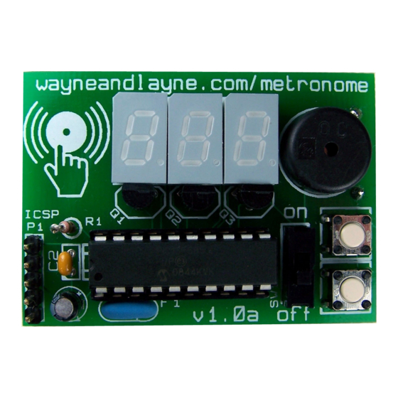
Tactile Metronome Home
Build Instructions, Printable Version
Step 0: Gather Tools
To build the Tactile Metronome, you will need a few common tools for soldering and electronics work. A
soldering iron and solder are the most important tools. You can use any soldering iron, although a higher-
quality, temperature-controlled adjustable iron will be easier to work with and give higher quality results. Any
standard solder for small electronics will do just fine.
To bend the leads of the push buttons, you will need a pliers or similar tool. We used the pliers on a wire
strippers. To trim the extra leads on the bottom of the pcb a diagonal pliers will work very well.
If you need some additional guidance and instruction on soldering, SparkFun, NASA, and
1 of 10
About
Forum
Tactile Metronome
Demos
Build
Use
http://www.wayneandlayne.com/projects/metron...
Open Source Hardware Kits
Video Game Shield
Contact
Parts List
Design
Download
Curious Inventor
Purchase
Projects
Tactile Metronome
Video Game Shield
Recent Articles
Efficient printing of USPS shipping labels
Tic-Tac-Toe game contributed to Video Game
Shield
Open Source Hardware Logo in Kicad
BP20422 Breakout Board
Fixing Linux firmware issues on Arduino Mega
2560
@wayneandlayne
New blog post: Stop wasting half your label when
printing USPS shipping labels:
http://tinyurl.com
/6gkn9uz 1 week ago
New contributed game for Video Game Shield:
Tic-Tac-Toe! More info, and downloads:
http://tinyurl.com/3owfow8 1 week ago
Yo dawg, we herd you like open source... (We
made a Kicad library for the OSHW logo)
http://goo.gl/te51e http://goo.gl/vr8tE 1 month ago
Tag Cloud
arduino
bluetooth
bp20422
camp class
education
contributed conway
event games
link
kicad
inkscape
life lifeconvert
dump
linux
mac makeday
makerfairesf2010
maker shed meta
nerdle
metronome ncp1400 NCP1400ASN50T1
open
open hardware
openhwsummit
source
oshw
open source hardware osh
tactile
projects software stem store
metronome
theremin tic tac toe tvout ubuntu
video game
video
shield
wayne and layne is awesome windows
05/11/2011 04:43 PM
pcb
Advertisement

Summary of Contents for Wayne and Layne Tactile Metronome
- Page 1 Step 0: Gather Tools Video Game Shield To build the Tactile Metronome, you will need a few common tools for soldering and electronics work. A soldering iron and solder are the most important tools. You can use any soldering iron, although a higher- Recent Articles quality, temperature-controlled adjustable iron will be easier to work with and give higher quality results.
- Page 2 Step 2: Push Buttons The push-buttons are used to adjust the settings of the Tactile Metronome, including pattern tempo and beep pitch. Use a pliers to straighten the legs of the buttons. They don’t need to be perfectly straight. We want the plastic base of the button to press right up against the PCB.
-
Page 3: Step 3: Electrolytic Capacitor
Build Instructions, Printable Version | Wayne and... http://www.wayneandlayne.com/projects/metron... Use your soldering iron to heat up the leg of the button and the ring around the hole at the same time. Push a little bit of solder on the ring. The solder should melt and flow around the hole. If you’re having trouble, make sure the tip of your iron is tinned and shiny. - Page 4 Build Instructions, Printable Version | Wayne and... http://www.wayneandlayne.com/projects/metron... To solder things with long legs like this, you can turn the board over and bend the legs a little bit, so the component doesn’t fall out while the board is upside-down. Solder the both legs to the PCB.
- Page 5 Build Instructions, Printable Version | Wayne and... http://www.wayneandlayne.com/projects/metron... over. Make sure the displays are firm against the board, and check for alignment.If the displays are crooked, you can reheat the junction and nudge the display. When you’re happy with the alignment, solder the remaining legs of the displays.
- Page 6 Build Instructions, Printable Version | Wayne and... http://www.wayneandlayne.com/projects/metron... Step 7: Chip Socket Insert the socket into the board. The footprint on the board is labeled J1. There is a notch in one end of the socket that should line up with the notch in the drawing on the PCB, next to the ceramic capacitor (C2) that was just installed.
- Page 7 Build Instructions, Printable Version | Wayne and... http://www.wayneandlayne.com/projects/metron... Step 9: Ceramic Resonator and Power Switch Insert the resonator (F1) and solder it down. Same goes for the power switch (SW1) . Both parts are not polarized, and can go either way into the board. There’s a line on the resonator footprint, but please ignore it. It will be removed in the next board revision.
- Page 8 Build Instructions, Printable Version | Wayne and... http://www.wayneandlayne.com/projects/metron... Step 11: In-Circuit Serial Programming Header (Optional) If you want to solder the ICSP header for reprogramming the microcontroller, you can do it now. You can use either a straight or right-angle header. The header is not provided. If you don’t have any header pins handy, you can unsolder the battery holder and attach the header later.
- Page 9 Build Instructions, Printable Version | Wayne and... http://www.wayneandlayne.com/projects/metron... Remove the paper backing from the foam tape on the battery holder, and insert the legs of the battery holder through the back of the holes in the PCB and slowly press the battery holder against the PCB. Be firm, but be careful not to warp the battery holder by pressing unevenly.
-
Page 10: Upcoming Events
Step 15: Give the completed board a final look over, checking for loose solder connections or shorted pads. Congratulations! You’re now the proud owner of a Tactile Metronome. Install some AAA batteries and give it a try!
Need help?
Do you have a question about the Tactile Metronome and is the answer not in the manual?
Questions and answers