Table of Contents
Advertisement
Quick Links
Advertisement
Table of Contents

Summary of Contents for AVALEX TECHNOLOGIES AVR8414
- Page 1 AVR8414 OPERATION MANUAL...
-
Page 2: Copyright Information
Avalex Technologies, the Avalex brand, Avalex logo, and any names of Avalex Technologies’ products mentioned in any part of this manual are trademarks of Avalex Technologies Corp. Any reproduction of Avalex Technologies’ names or logos mentioned in this manual or otherwise not connected with the reprinting of this manual for aiding the user is expressly prohibited without the express written permission of Avalex Technologies Corp. -
Page 3: Welcome
How to Use this Guide Please review the various sections of this guide prior to using the AVR8414 to become familiar with the device. Reading the Quick Start portion first will introduce the user quickly to the basic functions, and to button and encoder knob use. The rest of the manual is broken into sections providing detailed information on specific subject matter. -
Page 4: Table Of Contents
Set up a Reachback Recording through the Front Panel ..........20 Set up Reachback – Armed Mode ..................20 Setup Reachback – Triggered Mode .................20 Start Recording from Reachback ..................21 Configuration ..........................21 Display Outputs ........................21 Page | 3 of 105 AVR8414 Operation Manual – Rev O... - Page 5 UTC Offset ........................33 Ethernet ..........................34 Recorder Features ........................34 Managing Recording via Front Panel ..................34 Managing Recording via OSD ....................34 Setup/Start ........................35 Recording Options ........................36 Front Panel ........................36 MUTE ..........................36 EVENT ..........................36 Page | 4 of 105 AVR8414 Operation Manual – Rev O...
- Page 6 Line Select Channel Screen Status ...................48 Menu Softkey Controls ......................49 Softkey 1 ...........................49 Softkey 2 ...........................49 STATUS .........................49 DIM ..........................49 Communications (COMM) ....................50 Messages (MSGS) ......................50 Version (VER) ........................50 LOG ..........................51 Page | 5 of 105 AVR8414 Operation Manual – Rev O...
- Page 7 Configure ..........................65 Display ..........................65 Recording .........................67 Ethernet Input Recording ....................67 Playback ...........................68 Dimming ..........................69 Storage Configuration .......................70 Advanced Features ........................71 KLV Overlay ..........................71 TS Cloning ..........................72 Bandwidth Limits ........................73 Page | 6 of 105 AVR8414 Operation Manual – Rev O...
- Page 8 On-Screen Display Menu Diagram ..................84 Sample avr8414.ini Configuration file ..................85 Product Specifications ......................90 Avalex AVR8414 Factory Default Settings ................91 Avalex AVR8414 Dimming Legacy Default Settings ..............97 Photo Diagram ........................99 Formatting the SATA Drive ....................100 Product Care ........................101 Display Cleaning Recommendations ................101 Glossary ..........................
-
Page 9: Quick Start
The PWR LED will turn green when the recorder is ready for use. To turn the AVR off, remove power. Bezel Keys The AVR8414 includes a combination of soft bezel keys, switches, and an encoder knob. The bezel keys are grouped according to function as follows. Figure 1 - Bezel Button Configuration... - Page 10 Softkey 2 – Press to access system status and detail pages. Softkey 3 – Press to access live action record and playback controls. Softkey 4 – Press to turn the OSD menu on and off. Page | 9 of 105 AVR8414 Operation Manual – Rev O...
-
Page 11: Encoder Knob
1 below. If a mode is not active, it is skipped. For example, if the DVR is not recording or in playback, repeatedly pressing the knob will cycle between Mode 1 and Mode 5. Page | 10 of 105 AVR8414 Operation Manual – Rev O... - Page 12 Mode 3 applies to a special KLV overlay that can be displayed when KLV data is present in the video. This KLV overlay is described in more detail in the Advanced Features, KLV Overlay section of this manual. Page | 11 of 105 AVR8414 Operation Manual – Rev O...
-
Page 13: Cursor Mode
Figure 4 – Focus Blocks Storage Devices The AVR8414 comes equipped with one (1) internal and three (3) external storage options. The internal device has 54 GB of usable memory. The DVR has an external Universal Serial Bus (USB), a Secure Digital (SD) card, and a Solid State Drive (SSD) slot. The user can access the USB port by removing the rubber dust plug on the front panel. -
Page 14: Recommended Storage
USB 2.0 makes this port more suited for transfer of snapshots, video files, software updates, and data import/export. The following table can assist with calculating the amount of storage space required for a particular use case. Page | 13 of 105 AVR8414 Operation Manual – Rev O... - Page 15 Do not remove a storage device while the LED Status Sensor light is blinking or data/video may be compromised. Page | 14 of 105 AVR8414 Operation Manual – Rev O...
-
Page 16: Basic Functions - Front Panel
8. The selected video will play. Exit playback mode at any time by pressing the Stop recording or button. Once playback is complete, the Line Select Key will automatically return to RDY mode. Page | 15 of 105 AVR8414 Operation Manual – Rev O... -
Page 17: Video Passthrough
In Event Marker Skip mode, pressing the FF button on the front of the AVR8414 skips to a point in the video 4-6 seconds before the next event marker. This is to provide a buffer against video distortion if the video encoder is heavily burdened. -
Page 18: Playback While Recording
When the user decides to start a recording, the recorded reachback buffer will be prepended to the beginning of the record file so that the most recent reachback video will appear before the recording. Page | 17 of 105 AVR8414 Operation Manual – Rev O... -
Page 19: Set Reachback Time
SSD and INT allow for the full 3 minutes of Reachback time. Reachback to a USB Flash Drive or an SD card slower than Class 10 is not recommended. Page | 18 of 105 AVR8414 Operation Manual – Rev O... -
Page 20: Set Up A Reachback Recording Through The Osd
5. When ready to start the recording, select the “Rec Start” button from within the Channel Control area. Figure 8 – Reachback Time Figure 9 – Record Setup Page Page | 19 of 105 AVR8414 Operation Manual – Rev O... -
Page 21: Set Up A Reachback Recording Through The Front Panel
Once activated, the timer will begin counting the buffer currently recorded and display in five (5) second increments. Figure 11 – Reachback Triggered Mode Page | 20 of 105 AVR8414 Operation Manual – Rev O... -
Page 22: Start Recording From Reachback
Figure 12 – Record from Reachback Configuration Display Outputs The AVR8414 allows the user to configure the high definition output resolution and frame rate to best match the resolution of the display being used. Table 4 – Display Output The frame rate to select for the HD output will dictate... -
Page 23: Recorder Dimming
Recorder Dimming Bezel Lighting Areas Figure 13 - Bezel Lighting Areas The AVR8414 contains 15 buttons, a multi-color LED, and an OLED display. One of the three following inputs can be used to control the dimming: • Cockpit rheostat (potentiometer) input – either 5 VAC or 28VDC via input pin •... -
Page 24: Dimming Mode
To access the Dimming mode, navigate to the DIM page using the Softkey 2 button. Figure 14 - DIM Menu The AVR8414 supports three methods of dimming: photocell, rheostat, and luminance bezel buttons. These controls may be used separately. For instance, the photocell can be used for bezel brightness, while the display may be controlled by the potentiometer input. -
Page 25: Dimming Midpoint
The dimming ramp illustration (Figure 17, left) shows a linear ramp of 16 steps with a midpoint of 8. This linear ramp has smooth steps and equal luminance level steps above and below the midpoint. Page | 24 of 105 AVR8414 Operation Manual – Rev O... -
Page 26: Rheostat Limits
5V. The brightness will still follow the curve specified in the midpoint setting. If a midpoint of 8 is selected using the min/max voltages in this example, then when the voltage is 9.5V the brightness will be at 50% of the maximum luminance. Page | 25 of 105 AVR8414 Operation Manual – Rev O... -
Page 27: Set Dimming Options
The DSPLY option allows the user to adjust the minimum and maximum dimming levels to be used by the display when in day/night mode. Figure 22 - SETDIM DSPLY Screen Page | 26 of 105 AVR8414 Operation Manual – Rev O... -
Page 28: Bezel
Figure 23 - SETDIM BEZEL Screen Press and hold the day/night button for 20 seconds and press the ENT button to return to default dimming settings. Page | 27 of 105 AVR8414 Operation Manual – Rev O... -
Page 29: Discrete Setup
Discrete Setup The AVR8414 has three (3) discrete inputs that can be configured through the OSD to perform various actions. Record Start/Stop on Discrete State Change To configure a discrete to record, navigate to the OSD Main > Recording > Setup/Start page. -
Page 30: Zeroize On Discrete Edge
A discrete input can be configured to toggle the front panel between Day and Night dimming mode. Audio Input Mute on Discrete State Change A discrete input can be configured to mute/unmute input audio. Page | 29 of 105 AVR8414 Operation Manual – Rev O... -
Page 31: Discrete Output
Discrete Output Figure 26 – OSD Discrete Output Configure The AVR8414 has the hardware option of having a discrete output or stereo audio. AVR8414s with discrete output as an option can configure the discrete output to transition to an OPEN or CLOSED state based on the signal chosen. -
Page 32: Date/Time
Figure 27 – OSD Manual Date/Time NTP Date/Time The AVR8414 allows the user the option of retrieving the current date/time from an NTP (Network Time Protocol) Server. The default NTP server used is 129.6.15.30. This address can be changed in the “NTP Server IP Address” field. NTP will use SNTP (Simple Network Time Protocol) if SNTP is checked. - Page 33 NTP is updating. If NTP is enabled, a message may appear saying “NTP IN PROGRESS – REC START QUEUED”. This means that the recording will start once the NTP update has completed. Figure 29 -Record Start Queued Page | 32 of 105 AVR8414 Operation Manual – Rev O...
-
Page 34: Utc Offset
Once the recording starts, the message “DEQUEUE REC START” will appear. Figure 30 -Dequeue Record Start UTC Offset The AVR8414 gives the user the ability to change the current UTC offset. Figure 31 – OSD UTC Offset Page | 33 of 105... -
Page 35: Ethernet
Ethernet The AVR8414 is configured with a static IP address of 192.168.81.7 with subnet mask 255.255.0.0 and gateway 192.168.0.1 from the factory. The ethernet network configuration can be configured in the Configuration > Ethernet menu. The Multicast TTL (Time-To-Live) for ETH recording (TS streaming to UDP) and TS File streaming can be configured here as well. -
Page 36: Setup/Start
The user can select a target and overflow memory device, set the quality level of the recording, and enter an Ethernet streaming IP address. This menu also provides for configuration of the mark event function. Figure 34 – Record Setup / Start Page Page | 35 of 105 AVR8414 Operation Manual – Rev O... -
Page 37: Recording Options
DETAIL is selected. If a REC line select is chosen, record information will be shown. If a PLAY line select is chosen, playback file information will be shown. Page | 36 of 105 AVR8414 Operation Manual – Rev O... -
Page 38: Osd
To configure Overflow from the OSD, enter the Main Menu and select Recording. From the Setup/Start menu, select Channel 1 or 2 Setup. Select Yes in the Overflow menu. Figure 36 – Record Setup / Start Page Page | 37 of 105 AVR8414 Operation Manual – Rev O... -
Page 39: Quality
Other scenarios where starting a recording will result in the recording being queued temporarily are: • NTP time set is in progress • OSD Time Tab is open • File transfer is in progress • Zeroize is in progress Page | 38 of 105 AVR8414 Operation Manual – Rev O... - Page 40 Figure 38 – Record Queue 1 Figure 39 – Recording Queue 2 Page | 39 of 105 AVR8414 Operation Manual – Rev O...
-
Page 41: Pass-Through Video
To select a source for pass-through, highlight the row for the desired input and press the encoder to select that input. Figure 40 - OSD System/Input Channels Screen Page | 40 of 105 AVR8414 Operation Manual – Rev O... -
Page 42: Playback
FFW/RWD mode controls for the front panel's FFWD/RWD bezel buttons. A message will appear on the front panel stating EVENT MODE ENABLED or FFW/RWD MODE ENABLED, indicating the current mode. Page | 41 of 105 AVR8414 Operation Manual – Rev O... -
Page 43: Osd
Menu page. To play back from File Details, choose Play/Pause and press the encoder knob. The user may also stop, rewind, or fast-forward from this screen. Figure 42 - OSD File Details Screen Page | 42 of 105 AVR8414 Operation Manual – Rev O... -
Page 44: Ethernet Streaming
Ethernet Streaming The AVR8414 is capable of Ethernet streaming via UDP protocol using one or both channels. To configure the recorder for Ethernet streaming, access the Main Menu on the OSD and select Recording. From the Recording menu, select Setup/Start, choose Channel 1 or 2, and select a video source. - Page 45 Figure 44 – Ethernet Video Input Icons Figure 45 – Ethernet Video Input Page | 44 of 105 AVR8414 Operation Manual – Rev O...
-
Page 46: Front Display Menus
SD sources on the second line. HD sources are represented by a square icon and SD sources are represented by a circle icon. For more record options, see the section "Managing Recordings via OSD.” Page | 45 of 105 AVR8414 Operation Manual – Rev O... -
Page 47: Modes
The playback target is either the most recent file or a pre- selected file from the file list. The Play mode alerts users that the channel is being used to play back a video PLAY file. Page | 46 of 105 AVR8414 Operation Manual – Rev O... -
Page 48: Storage
Storage The AVR8414 has USB, SD, SSD, and internal memory (INT), indicated by the second pull- down box in the Line Select Key. Figure 46 - Storage Screen Video Devices The user can connect up to two (2) HD and four (4) SD video sources into the recorder. Once a source has been selected, the HD (indicated by a box) or SD (indicated by a circle) will be highlighted with an inverted fill, as demonstrated in Figure 44. -
Page 49: Line Select Channel Screen Status
Line Select Channel Screen Status Once the video source and memory have been selected, the screen will show current status and device information including the following: Figure 48 - Channel Screen Status Page | 48 of 105 AVR8414 Operation Manual – Rev O... -
Page 50: Menu Softkey Controls
The status screen shows the the total run time in hours, the total power cycles, device temperature, voltage, and current for various devices. For a complete explanation of DIM, please refer to the Configuration section of this manual. Page | 49 of 105 AVR8414 Operation Manual – Rev O... -
Page 51: Communications (Comm)
Currently the message screen is the (CAS) Crew Alert Screen. Version (VER) The version screen displays the AVR’s unique identification number and the current software version that is installed on the recorder Page | 50 of 105 AVR8414 Operation Manual – Rev O... -
Page 52: Log
Avalex. MEMORY The memory screen shows the user how much memory is available on the storage devices currently connected to the recorder. Figure 54 - Memory Screen Page | 51 of 105 AVR8414 Operation Manual – Rev O... -
Page 53: List Configuration (Lcfg)
Softkey 3 provides the user with information on a recording/playback file and allows the user to execute immediate commands to change recording characteristics. Figure 56 - Softkey 3 Menu Page | 52 of 105 AVR8414 Operation Manual – Rev O... -
Page 54: Event
Softkey 4, when pressed, will activate the On-screen Display menu. Press the softkey again to deactivate the menu. Figure 57 - Softkey 4 Press the Clear or button to exit any menu and return to the previous screen or action. Page | 53 of 105 AVR8414 Operation Manual – Rev O... -
Page 55: On-Screen Display Menus
The Order selection will allow the user to change the list from ascending or descending. File can also be filtered by storage device or by media type. Pressing the Play button while the cursor is highlighting a file will play the file. Page | 54 of 105 AVR8414 Operation Manual – Rev O... -
Page 56: File Details
After selecting a file, the user can copy and move the file to another storage device. The user can also delete or play the selected file. Figure 60 - File Details Menu Page | 55 of 105 AVR8414 Operation Manual – Rev O... -
Page 57: File Naming Convention
“Disable Tagging” option. The Move and Copy buttons are only enabled if all tagged files are located on the same disk. Figure 61 - File Tagging Page | 56 of 105 AVR8414 Operation Manual – Rev O... -
Page 58: Jpeg Viewer
JPEG Viewer The AVR8414 has the option of quickly viewing JPEGs with a next and previous button for cycling through images. To access this special mode, press the button while the cursor is on a JPEG file (Figure 60). Figure 62 - JPEG Viewer System The System Menu provides status information on the various components of the recorder. -
Page 59: Input Channels
Filled (white or green) – input is selected for recording Figure 64 - Input Channels Menu Status Select Status to view system information including current, temperature, date, time, built-in- tests, software revisions, and discretes. Page | 58 of 105 AVR8414 Operation Manual – Rev O... -
Page 60: Storage
(INT or SSD). If the device in question is the SSD, remove and reinsert. For any other device type, power cycle the DVR either by removing power or by holding down the encoder knob for 10 seconds. Page | 59 of 105 AVR8414 Operation Manual – Rev O... -
Page 61: Log File
The system data log records can be viewed, sorted, and exported from the Log File menu. An external media device must be installed in the recorder for the export function to be enabled. Figure 66 – Log File Menu Page | 60 of 105 AVR8414 Operation Manual – Rev O... -
Page 62: Software Update
8 characters in length. Write down the passcode in this space: _ _ _ _ _ _ _ _ Contact Avalex to receive a Master Passcode if your passcode is lost. Page | 61 of 105 AVR8414 Operation Manual – Rev O... - Page 63 Figure 68A – OSD Passcode Entry Page Figure 68B - System Admin Menu Page | 62 of 105 AVR8414 Operation Manual – Rev O...
-
Page 64: Configuration File
Configuration File The AVR settings can be loaded from a configuration avr8414*.ini file. In order to provide the settings, the configuration file must be loaded onto an SD, SSD, or USB storage device and then uploaded to the unit through the configuration page. This is done by selecting the storage device and then selecting Upload. -
Page 65: Configuration Status
A lock symbol will appear on the left of the bottom status bar when a configuration is locked. Configuration Lock can be disabled from the System > Configuration File Menu. Page | 64 of 105 AVR8414 Operation Manual – Rev O... -
Page 66: Configure
Select. If a Line-Select is not active, this mode of pass-through selection will not be available. The Hide OSD for Snapshots option can be set to hide the OSD overlays whenever a snapshot is taken. Page | 65 of 105 AVR8414 Operation Manual – Rev O... - Page 67 Auto Passthrough attempts to set passthrough to the first active record channel under these circumstances: • A recording is started. • Playback is stopped. • A video input is detected or lost. Figure 72 - Display Configuration Menu Page | 66 of 105 AVR8414 Operation Manual – Rev O...
-
Page 68: Recording
Ethernet icon will appear as an available video input indicated by a hexagon with an E inside. This icon can be selected for recording. The icon will change to green when the UDP stream is detected at the Ethernet port. Page | 67 of 105 AVR8414 Operation Manual – Rev O... -
Page 69: Playback
“TS File Streaming.” If this option is set to Yes, a playback option will appear when viewing File Details on the OSD page Main > File List > File Details. Figure 74 - Playback Configuration Menu Page | 68 of 105 AVR8414 Operation Manual – Rev O... -
Page 70: Dimming
In addition to controlling the dimming settings through the front panel DIM page, the dimming settings can be changed from the OSD Configure > Dimming menu. Figure 76 - Dimming Configuration Page Page | 69 of 105 AVR8414 Operation Manual – Rev O... -
Page 71: Storage Configuration
If a device is disabled, it will not be available for recording, playback, log export, or as a software update or configuration file source. Figure 77 - Storage Configuration Menu Page | 70 of 105 AVR8414 Operation Manual – Rev O... -
Page 72: Advanced Features
Advanced Features KLV Overlay The AVR8414 offers the capability of viewing KLV data as an overlay of the recorded video. The recorded video must contain certain KLV data fields in order for the data to be displayed (Figure 76). The data fields the video is capable of displaying are described in the table below. -
Page 73: Ts Cloning
TS Cloning The AVR8414 has the option of cloning a recording to a second memory target, allowing the TS file to be duplicated in real time. To enable TS cloning, navigate to the OSD menu > Configure > Recording and enable the Clone TS File option by selecting Yes in the dropdown. -
Page 74: Bandwidth Limits
Bandwidth Limits The AVR8414 is able to record multiple sources and perform playback simultaneously. While flexible, the system needs careful control during recording and playback due to the bandwidth limitations. Only one (1) HD input at a time may be recorded on each Line Key or Channel. -
Page 75: Troubleshooting Guide
The <#> in RBK<#> and REC<#> can be 1 or 2, indicating the recording channel. • <TS-FILE-NAME> is the name of the file saved during a recording or a file used for playback. • <SOURCE> represents the video source format. Page | 74 of 105 AVR8414 Operation Manual – Rev O... - Page 76 EXPORT IS BUSY. EXPORT IS BUSY PLEASE WAIT... 15 A playback start was requested while a file FILE TRANSFER BUSY. FILE TRANSFER BUSY transfer was in progress. PLEASE WAIT... Page | 75 of 105 AVR8414 Operation Manual – Rev O...
- Page 77 CANNOT HAVE IDENTICAL IP PORT NUMBERS 28 Streaming two Ethernet UPD streams to REC<#> CANNOT HAVE the same IP port is not allowed. THE SAME IP PORT AS PLAYBACK STREAMING Page | 76 of 105 AVR8414 Operation Manual – Rev O...
- Page 78 CONFIG WHILE PLAY OR REACHBACK IS ACTIVE 43 Configuration import failed because the LOAD FAILED. ERROR: LOAD FAILED configuration source storage device was <STORAGE DEVICE> not found. NOT FOUND Page | 77 of 105 AVR8414 Operation Manual – Rev O...
- Page 79 TRY AGAIN. CAPTURE cannot be restarted because it is in use (for RECONFIG NEEDED play or record). 59 Record or reach-back start failed at CODEC. <REC/RBK><#> START <REC/RBK><#> START FAIL FAIL Page | 78 of 105 AVR8414 Operation Manual – Rev O...
- Page 80 – possibly due to a slow storage device. 73 An attempt was made to transfer file(s) CANNOT TRANSFER STOP REC TO TRFR while recording is active. FILE(S) WHEN RECORD IS ACTIVE! Page | 79 of 105 AVR8414 Operation Manual – Rev O...
- Page 81 DISK SLOW LIMIT (USB or SD) and cannot support writing of RBK<#> TO 30 SEC RBK<#> TO 30 SEC large reach-back buffers – reach-back has been limited to 30 seconds. Page | 80 of 105 AVR8414 Operation Manual – Rev O...
- Page 82 102 A recording was aborted because the FILE WRITE FAIL - FILE WRITE FAIL - record file size did not change for 10 <REC#> ABORT! REC<#> seconds. Page | 81 of 105 AVR8414 Operation Manual – Rev O...
-
Page 83: Connector/Interface Pinout
Connector/Interface Pinout J1 – Power / Communications AVR8414 Mating Cable Display Connector Connector D38999/26WC35SN (Plug) D38999/24WC35PN M85049/38S13W (Strain Relief) SIGNAL +28VDC PWR PWR GND DIMMING-5 VDC/28 VDC/5 VAC AUDIO GND AUDIO LEFT IN AUDIO LEFT OUT DISCRETE INPUT 1 (OPEN/GROUND) -
Page 84: Alternate Communications Interface Pinout
Alternate Communications Interface Pinout Avalex offers the AVR8414 with two I/O options. The standard configuration shown above features stereo audio in/out. The alternate configuration show below features a discrete output for remote triggering of equipment. J1 – Power / Communications AVR8414-11... -
Page 85: Appendix
On-Screen Display Menu portion of this manual. Menus circled in red are pass-code protected if pass-code protection is enabled. Figure 81 - OSD Menu Tree Page | 84 of 105 AVR8414 Operation Manual – Rev O... -
Page 86: Sample Avr8414.Ini Configuration File
#dimOnDiscreteId options are 1, 2, 3 or 0 (disabled), ** defaults to 0 dimOnDiscreteId=0 #dimOnDiscreteState only applicable if dimOnDiscreteId=1 or 2 or 3 options are open or ground Page | 85 of 105 AVR8414 Operation Manual – Rev O... - Page 87 #potentiometerType options are 28V, 5V potentiometerType=5V #midPointDay options are -1, 2 thru 15 ** defaults to -1 (calibrated defaults) midPointDay=-1 #midPointNight options are -1, 2 thru 15 ** defaults to -1 (calibrated defaults) Page | 86 of 105 AVR8414 Operation Manual – Rev O...
- Page 88 #clone options are: NONE, INT, SSD, SD (may not be the same as target). Note1: overflow is disabled if clone is enabled. ** defaults to NONE #overflow options are: yes or no -- if yes then overflow device will be next device in storagePriority. ** defaults to no Page | 87 of 105 AVR8414 Operation Manual – Rev O...
- Page 89 #tsFileStreaming options are yes or no, ** defaults to no -- if set to yes the OSD file details page will # have controls to start/stop TS file streaming tsFileStreaming=no #udp-ip for example: udp-ip=192.168.1.44 Note1: required parameter if tsFileStreaming=yes udp-ip=192.168.1.50 Page | 88 of 105 AVR8414 Operation Manual – Rev O...
- Page 90 #enableSD options are yes or no, ** defaults to yes, the removable SD drive will be disabled if set to no #enableUSB options are yes or no, ** defaults to yes, the removable USB drive will be disabled if set to no enableUSB=yes Page | 89 of 105 AVR8414 Operation Manual – Rev O...
-
Page 91: Product Specifications
Audio Stereo or 1 Input; 1 Output Audio Mono 1 Inputs; 1 Output Audio Mono * 2 Inputs; 2 Outputs Discretes 3 Inputs; 1 Output Discretes 3 Inputs * Software configurable Page | 90 of 105 AVR8414 Operation Manual – Rev O... -
Page 92: Avalex Avr8414 Factory Default Settings
Discrete an event mark be placed in video. (disabled) Event Mark Selects whether an open or ground Falling (Ground), Open Trigger signal will trigger the event mark. Rising (Open) Page | 91 of 105 AVR8414 Operation Manual – Rev O... - Page 93 Simple Network Time messages. UTC Offset Sets the universal coordinated time -12 - 14 offset of the DVR. Network DVR IP Sets the IP address of the AVR8414. ###.###.###.### 192.168.81.7 Address DVR IP Sets the subnet mask of the ###.###.###.### 255.255.0.0 Netmask AVR8414 network adapter.
- Page 94 5V Max from the 5V dimming bus input (if configured). Potentiometer Sets the minimum value expected 0 - 28000 28V Min from the 28V dimming bus input (if configured). Page | 93 of 105 AVR8414 Operation Manual – Rev O...
- Page 95 USB, ETH, NONE recordings. Overflow Selects whether the overflow feature Yes, No is turned on; overflow will automatically follow the storage priority settings when the primary media becomes full. Page | 94 of 105 AVR8414 Operation Manual – Rev O...
- Page 96 USB, ETH, NONE recordings. Overflow Selects whether the overflow feature Yes , No is turned on; overflow will automatically follow the storage priority settings when the primary media becomes full. Page | 95 of 105 AVR8414 Operation Manual – Rev O...
- Page 97 Playback Disable Disables the recorded audio for Yes, no Playback videos during playback only. Does Audio not affect audio recording. Page | 96 of 105 AVR8414 Operation Manual – Rev O...
-
Page 98: Avalex Avr8414 Dimming Legacy Default Settings
Avalex AVR8414 Dimming Legacy Default Settings Configuration Feature Explanation Valid Settings Selected Option Dimming OLED Control Selects the signal which controls the Plus-minus- Plus-minus- dimming level of the front panel buttons, photo- buttons OLED screen. cell, potentiometer Bezel Control Selects the signal which controls the... - Page 99 28V Min from the 28V dimming bus input (if configured). Potentiometer Sets the maximum value expected 0 - 28000 28000 28V Max from the 28V dimming bus input (if configured). Page | 98 of 105 AVR8414 Operation Manual – Rev O...
-
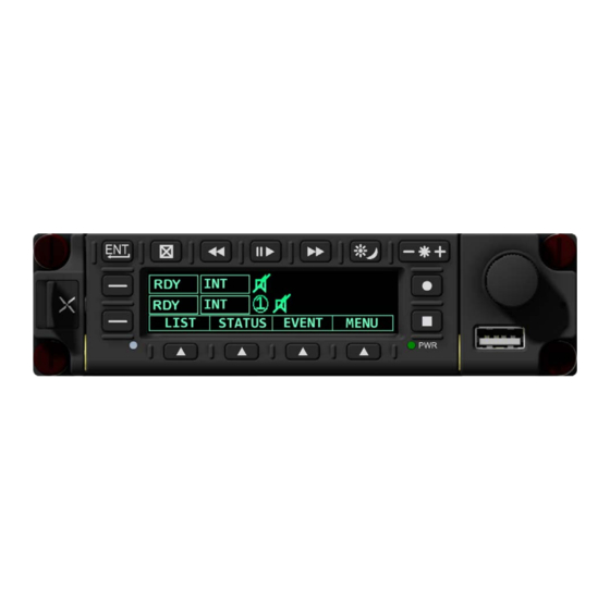
Page 100: Photo Diagram
Photo Diagram Below is a photo diagram of an AVR8414 HD Digital Video Recorder. This image is for reference only. This photo diagram is not intended to substitute for product interconnect drawings. To obtain a current interconnect drawing, please contact Avalex Technologies. -
Page 101: Formatting The Sata Drive
Reformatting the storage device whenever it is connected to a PC for data retrieval is recommended. Be sure to select the correct drive when formatting to FAT32. Formatting the drive to FAT32 will erase all data on that drive. Page | 100 of 105 AVR8414 Operation Manual – Rev O... -
Page 102: Product Care
The following information will help in caring for Avalex Technologies products. Display Cleaning Recommendations To avoid scratches or other damage to products, Avalex Technologies recommends following these cleaning instructions. 1. For dry sand or dirt, gently brush it away with a soft natural hair brush. -
Page 103: Glossary
Available files displayed from the cockpit display unit LISTO Available files displayed in the recording device display MSGS Messages On-Screen Display Personal Computer PLYA Playback PRVA Previous Setting Playback While Record Reachback Armed Reachback Triggered Ready Page | 102 of 105 AVR8414 Operation Manual – Rev O... - Page 104 Set Dimming SET NT DIM LVL Set Night Dimming Level SNAP Snapshot or video image Solid State Drive Universal Serial Bus Universal Time Coordinate Voltage AC Volts Direct Current Version Page | 103 of 105 AVR8414 Operation Manual – Rev O...
-
Page 105: Warranty Information
(ii) Customer’s payments of all invoices for the Products or other charges to which Avalex Technologies may be entitled, (iii) Customer’s exclusive use of persons approved or authorized by Avalex Technologies to effect any repairs to the products, and (iv) Customer’s substantiation that no modification or... -
Page 106: Technical Support Information
This warranty does not cover failure due to abuse, misuse, accident, or unauthorized alterations or repairs and covers only material defects that appear under normal use. Avalex Technologies’ liability and Customer’s exclusive remedy for defective Products shall be limited solely to repair or replacement.
Need help?
Do you have a question about the AVR8414 and is the answer not in the manual?
Questions and answers