
Summary of Contents for Quadlogic MiniCloset-5c
- Page 1 Table of Contents Manual Dimensional Drawing Residential Installation Diagrams (US) Residential Installation Diagrams (Canada)
- Page 2 MiniCloset-5c Installation Manual Quadlogic Controls Corporation © COPYRIGHT 2009...
-
Page 3: Table Of Contents
Warning ....................1 Disclaimer .....................1 Symbols ....................1 Chapter 1 Introduction Overview....................3 Power Line Communications (PLC) ............3 Scan Transponder-5 (PLC Data Collector and Communicator)......3 Quadlogic Metering System ..............4 Chapter 2 About the MiniCloset-5c The MiniCloset-5c ...................6 Specifications..................7 Chapter 3 Parts and Options Parts.....................9 Options ....................9... - Page 4 Warranty Information................75 Release Dates ..................75 Revision History ................... 75 Appendix The Communications Module ..............76 RS-485 Overview.................. 79 Guidelines for Proper Wiring of a RS-485 Network ........79 The Pulse Datalogger Module..............85 Quadlogic Controls Corporation © COPYRIGHT 2009...
-
Page 5: Contact Information
Thank you for purchasing a MiniCloset-5c multi-channel electric power meter manufactured by Quadlogic Controls Corporation. Quadlogic has been designing, manufacturing, and selling digital electric metering systems for over 25 years. We appreciate your business. ONTACT NFORMATION For sales and technical support, please contact Quadlogic Controls Corporation as indicated below. - Page 6 Quadlogic Controls Corporation © COPYRIGHT 2009...
-
Page 7: Introduction
OLLECTOR AND OMMUNICATOR When the MiniCloset-5c is read via PLC, one or more Scan Transponder-5’s are required. The Scan Transponder-5 is the central data collector for Quadlogic metering systems. It communicates with Quadlogic meters over the existing electric wires that serve each tenant in a building or customer on a utility grid. -
Page 8: Quadlogic Metering System
This metering system measures electrical usage for each tenant (customer), cost center, or common area space, and communicates this metering data over the power distribution wires. A metering system is comprised of two or more Quadlogic electricity meters and at least one Quadlogic Scan Transponder-5 (ST-5), which is Quadlogic’s data collector and concentrator. - Page 9 Chapter 1 Introduction Figure 1-2. Typical Quadlogic metering system. Quadlogic Controls Corporation © COPYRIGHT 2009...
-
Page 10: About The Minicloset-5C
LOSET LOSET The MiniCloset-5c, or MC-5c, is a multi-tenant digital electric meter used for commercial, residential or industrial applications. It meters up to 24 circuits or channels, which can be configured as 24 single-phase/circuit loads, 12 two-phase/circuit loads, 8 three-phase/circuit loads, or any equivalent combination. -
Page 11: Specifications
Open-source data conversion program Collects data from up to 12 water, gas, or BTU meters Form A Dry Contact Inputs PDM connects to MiniCloset-5c via CAT5 Maximum 4 PDM units to a MC-5c (daisy chain) Total of 48 discrete inputs total... - Page 12 Industry Canada: MC# AE-1148 Communications Options Although a MiniCloset-5c is typically part of an AMR (Automatic Meter Reading) System whereby metering data is collected by a Scan Transponder using PLC, in some cases a user may need to communicate with the meter directly. In addition to the Power Line...
-
Page 13: Parts And Options
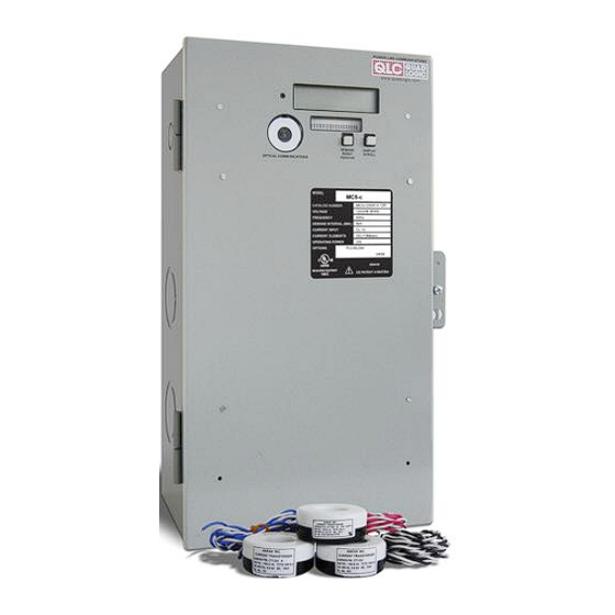
ARTS Figure 3-1. MiniCloset-5c, Parts and Assembly A. Meter Head – Main component of the MiniCloset-5c. The Meter Head contains the Meter Module, through which all signals transmit, events are recorded and meter data is stored. B. Voltage Connector – A 14-pin connector that connects the Fuse Block (C) and the Meter Head (A). - Page 14 II. RS-485 The Data Link External Communications or RS-485 module allows multiple Quadlogic meters to be connected together in cases where PLC is not being utilized. RS-485 utilizes two (2) shielded, twisted pairs of #16 AWG stranded wires.
- Page 15 Parts and Options V. Interface with Quadlogic Software (IQ) The Interface with Quadlogic (IQ) Program allows for easy access to all metering information necessary for basic bill generation, daily load profiling and certain customer service functions such as acquiring as needed reads for customers moving into or out of a designated location.
- Page 16 Chapter 3 Parts and Options Quadlogic Controls Corporation © COPYRIGHT 2009...
-
Page 17: Installation
NSTALLATION VERVIEW This chapter contains installation instructions and wiring diagrams for all MiniCloset-5c meter models. The installation instructions start with a general procedure which applies to all meter models, then continues with specific wiring and CT installation information for each particular MC-5c configuration. -
Page 18: Installation Instructions For Meter, Mci, And Cts
Certification requires a visual inspection of the current transformers and the voltage taps on the incoming feeder phase wires. The MiniCloset-5c installation procedure consists of the following steps: 1. Install metal box 2. Optional communication module is installed, run communications wiring 3. - Page 19 #12 AWG stranded wire with white insulation. 3. Run the #12 AWG feeder phase tap wires through the conduit to the MC-5c back box. Connect the wires to the MiniCloset-5c Fuse Block. Step 4: Install and connect Current Transformers (CTs)
- Page 20 CT go to the corresponding pair of screw terminals on the MCI. For example, if the black wire from a CT goes to terminal “I1”, then the white wire from that same CT Quadlogic Controls Corporation © COPYRIGHT 2009...
- Page 21 The meter is ready for testing and certification. CAUTION: When reading the meter display, all consumption and demand values must be multiplied by the correct multiplier to calculate true value. Please refer to Chapter 6: Applying Multipliers. Quadlogic Controls Corporation © COPYRIGHT 2009...
-
Page 22: Wiring Overview
Detailed wiring instructions A) Voltage taps Follow voltage tap installation procedure on page 15. Color-code the main feeder wires as follows: Black – phase A; Red – Phase B; Blue – phase C; White – Neutral. Quadlogic Controls Corporation © COPYRIGHT 2009... - Page 23 (Black, Red, or Blue). iii. Route the load wire through the CT as shown in the diagram iv. Connect the CT secondary wires to the MCI according to the following procedure: Quadlogic Controls Corporation © COPYRIGHT 2009...
- Page 24 1. For Commercial (designated with “C”) 3-phase/4-wire model, each A-B-C combination is a single meter point: Meter #1 (M#1) is CT1, CT2, and CT3 Meter #2 (M#2) is CT4, CT5, and CT6 Repeat for M#3 to M#8 Quadlogic Controls Corporation © COPYRIGHT 2009...
- Page 25 If breakers are energized, shorting links must be installed before: a) Disconnecting the CT headers or b) Replacing or installing meter heads on the panel. WARNING: Bodily injury or damage may result if shorting links are not installed. Quadlogic Controls Corporation © COPYRIGHT 2009...
- Page 26 Chapter 4 Installation Figure 4-5. 3-phase, 4-wire wye wiring Quadlogic Controls Corporation © COPYRIGHT 2009...
- Page 27 Chapter 4 Installation Quadlogic Controls Corporation © COPYRIGHT 2009...
- Page 28 Chapter 4 Installation Quadlogic Controls Corporation © COPYRIGHT 2009...
-
Page 29: 1-Phase, 3-Wire 120/208V Wiring (Network)
If required, run the hot wires through a disconnect switch (if fused, use 15A ‘Fast Acting’ fuses.) Run wires through conduit to MC-5c back box. Connect to screw terminals on fuse block. Black – VA; Red – VB; Blue – VC; White – N Quadlogic Controls Corporation © COPYRIGHT 2009... - Page 30 2. Each A-B, C-A, and B-C combination is a single meter point (separated by yellow and white in the above chart): Meter #1 (M#1) is measuring CT1 and CT2 Meter #2 (M#2) is measuring CT3 and CT4 repeat for M#3 to M#12 Quadlogic Controls Corporation © COPYRIGHT 2009...
- Page 31 If breakers are energized, shorting links must be installed before: a) Disconnecting the CT headers or b) Replacing or installing meter heads on the panel. WARNING: Bodily injury or damage may result if shorting links are not installed. Quadlogic Controls Corporation © COPYRIGHT 2009...
- Page 32 Chapter 4 Installation Figure 4-7. 1-phase, 3-wire 120/208V wiring Quadlogic Controls Corporation © COPYRIGHT 2009...
- Page 33 Chapter 4 Installation Quadlogic Controls Corporation © COPYRIGHT 2009...
- Page 34 Chapter 4 Installation Quadlogic Controls Corporation © COPYRIGHT 2009...
-
Page 35: 3-Phase, 3-Wire Delta Wiring
Connect #12 AWG wires to phase A, phase B, and phase C. Wires must be Black (phase A), Red (phase B), and Blue (phase C). iv. If required, run the hot wires through a disconnect switch (if fused, use 15A ‘Fast Acting’ fuses.) Quadlogic Controls Corporation © COPYRIGHT 2009... - Page 36 1. Current transformers must be in phase with Reference Voltage. The MCI runs in an A-C phase rotation (See Figure 4-8) and each two CT connections repeat an A-C, A- C, A-C pattern Quadlogic Controls Corporation © COPYRIGHT 2009...
- Page 37 If breakers are energized, shorting links must be installed before: a) Disconnecting the CT headers or b) Replacing or installing meter heads on the panel. WARNING: Bodily injury or damage may result if shorting links are not installed. Quadlogic Controls Corporation © COPYRIGHT 2009...
- Page 38 Chapter 4 Installation Figure 4-9. 3-phase, 3-wire delta wiring Quadlogic Controls Corporation © COPYRIGHT 2009...
- Page 39 Chapter 4 Installation Quadlogic Controls Corporation © COPYRIGHT 2009...
- Page 40 Chapter 4 Installation Quadlogic Controls Corporation © COPYRIGHT 2009...
-
Page 41: 3-Phase, 4-Wire 1El Wiring
(Black, Red, or Blue). iii. Route the load wire through the CT as shown in the diagram iv. Connect the CT secondary wires to the MCI according to the following procedure: Quadlogic Controls Corporation © COPYRIGHT 2009... - Page 42 CT1, CT4, CT7, etc. Current transformers installed in phase with B reference voltage must be installed on CT2, CT5, CT8, etc. Current transformers installed in phase with C reference voltage must be installed on CT3, CT6, CT9, etc. Quadlogic Controls Corporation © COPYRIGHT 2009...
- Page 43 If breakers are energized, shorting links must be installed before: a) Disconnecting the CT headers or b) Replacing or installing meter heads on the panel. WARNING: Bodily injury or damage may result if shorting links are not installed. Quadlogic Controls Corporation © COPYRIGHT 2009...
- Page 44 Chapter 4 Installation Figure 4-11. 3-phase, 4-wire 1EL wiring Quadlogic Controls Corporation © COPYRIGHT 2009...
- Page 45 Chapter 4 Installation Quadlogic Controls Corporation © COPYRIGHT 2009...
- Page 46 Chapter 4 Installation Quadlogic Controls Corporation © COPYRIGHT 2009...
-
Page 47: 1-Phase, 3-Wire 240V 1El Wiring
If required, run the hot wires through a disconnect switch (if fused, use no less than 15A ‘Fast Acting’ fuses.) Run wires through conduit to MC5 back box. Connect to screw terminals on fuse block. Black – VA; Red – VB. Quadlogic Controls Corporation © COPYRIGHT 2009... - Page 48 (M#1) to Meter #24 (M#24). The number of CT terminal and meter connections will depend on the number of suites available. For example: - M#1 connects to CT#1 - M#2 connects to CT#2 - Repeat for M#3 to M#24 Quadlogic Controls Corporation © COPYRIGHT 2009...
- Page 49 If breakers are energized, shorting links must be installed before: a) Disconnecting the CT headers or b) Replacing or installing meter heads on the panel. Bodily injury or damage may result if shorting links are not installed. Quadlogic Controls Corporation © COPYRIGHT 2009...
- Page 50 Chapter 4 Installation Figure 4-13. 1-phase, 3-wire 1EL wiring Quadlogic Controls Corporation © COPYRIGHT 2009...
- Page 51 Chapter 4 Installation Quadlogic Controls Corporation © COPYRIGHT 2009...
- Page 52 Chapter 4 Installation Quadlogic Controls Corporation © COPYRIGHT 2009...
-
Page 53: 1-Phase, 3-Wire 240V 2El Wiring
If required, run the hot wires through a disconnect switch (if fused, use no less than 15A ‘Fast Acting’ fuses.) Run wires through conduit to MC-5c back box. Connect to screw terminals on fuse block. Black – VA; Red – VB. Quadlogic Controls Corporation © COPYRIGHT 2009... - Page 54 Line 2 (Wire 2): Line 2 should be passed through the CT from the side WITHOUT the dot/H1 marking. Note that these are opposite polarities (see Figure 4-14). Figure 4-14. Line 1 and Line 2 passed through two different current transformers. Quadlogic Controls Corporation © COPYRIGHT 2009...
- Page 55 If breakers are energized, shorting links must be installed before: a) Disconnecting the CT headers or b) Replacing or installing meter heads on the panel. Bodily injury or damage may result if shorting links are not installed. Quadlogic Controls Corporation © COPYRIGHT 2009...
- Page 56 Chapter 4 Installation Figure 4-15. 1-phase, 3-wire 240V 2EL wiring Quadlogic Controls Corporation © COPYRIGHT 2009...
- Page 57 Chapter 4 Installation Quadlogic Controls Corporation © COPYRIGHT 2009...
- Page 58 Chapter 4 Installation Quadlogic Controls Corporation © COPYRIGHT 2009...
-
Page 59: Using The Meter
Menu. For example, if the meter is in FORWARD mode and the Display Scroll button is released when the LCD reads “Serial # Registers”, each subsequent depression of the Display Scroll button will show the following, in the order it appears below: Quadlogic Controls Corporation © COPYRIGHT 2009... - Page 60 FORWARD is displayed. Caution: When reading the meter display, all consumption and demand values must be multiplied by the correct multiplier to calculate true value. Please refer to Chapter 6 for more details. Quadlogic Controls Corporation © COPYRIGHT 2009...
- Page 61 Chapter 5 Using the Meter Figure 5-2. The Display Menu Structure For an 8-meter point MC-5c. Quadlogic Controls Corporation © COPYRIGHT 2009...
-
Page 62: Verifying Meter Functionality
It is very important to verify that the MC-5c and the CTs are properly installed. Follow the steps below to verify the voltage, kWh reading, current, and energy. I. Verifying Voltage 1. Press and hold the Display Scroll button until the following menu heading is displayed: Quadlogic Controls Corporation © COPYRIGHT 2009... - Page 63 The W(att) reading is the indication of power. The W(att) reading will also count forward when viewed on the LCD. A negative power reading is indicative of an incorrectly installed CT, or one that is cross-phased with the wrong voltage (phase) leg. The R(eactive) reading Quadlogic Controls Corporation © COPYRIGHT 2009...
-
Page 64: Resetting Demand Values (For Commercial Applications Only)
Transponder or software.) 1. Press and hold the Demand Reset button. 2. The LCD will initially display the Quadlogic Copyright message. 3. The LCD will then display the Dmdreset event screen: 4. -
Page 65: Applying Multipliers
Table 6.1 Standard multiplier table. Meter Boltage Multiplier for Multiplier for CT Rating Ratings 0.1A CT 5.0A CT For 240V 100A X0.5 X20.0 (Split-phase) 200A X1.0 X40.0 Table 6.2 Multiplier table for a 240V split-phase MiniCloset-5c meter. Quadlogic Controls Corporation © COPYRIGHT 2009... -
Page 66: How Ct Multipliers Are Calculated
(as shown in Table 6.2). This is due to the fact that internal multipliers were already applied in the meter during the calibration process. Failure to use the appropriate multiplier will result in an incorrect diagnosis of the meter’s functionality and incorrect revenue billing. Quadlogic Controls Corporation © COPYRIGHT 2009... -
Page 67: Overview
OMMUNICATIONS VERVIEW In addition to integrated PLC, Quadlogic meters have an optical port as a standard feature and an optional modem, RS-232, or RS-485 module through which communications with the meter can be established. Any computer with a terminal emulation program such as HyperTerminal Private Edition can be utilized. - Page 68 5. Go to the Properties window and select the Settings tab. Go to the ASCII Setup and check the “Echo typed characters locally” box. Click on OK. Figure 7-4. ASCII Setup Window Once HyperTerminal is setup, the user can now log in into the meter. Quadlogic Controls Corporation © COPYRIGHT 2009...
-
Page 69: Security Hierarch
ECURITY IERARCH Quadlogic meters are protected by a security hierarchy of Level 1 (least secure) through Level 5 (most secure). Each level allows access to increasing data parameters and manipulation of the meter. Once logged in at the specific level, access to that level and all those levels below it are permitted. -
Page 70: Basic Meter Data
Chapter 7 Communications Once the login string has been delivered, the Quadlogic meter will display a Quadlogic Copyright message followed by the “CIP#” prompt. The “CIP#” prompt is the indication that the login was successful and the next command can be entered. - Page 71 1#4 as 4/13/2005 and so on. Combine the desired Q# (Billing Quantity) and 1# (day number) to request the specific data. The above table lists all the interval data for Q#1 (kW) on 1#6 (4/15/2005) in block form. Quadlogic Controls Corporation © COPYRIGHT 2009...
- Page 72 3) Excel Spreadsheet Form Entering the command mdw_-E<enter> will list all interval log data in a format that can be imported into Excel. The date column will then need to be formatted to an Excel format. Quadlogic Controls Corporation © COPYRIGHT 2009...
-
Page 73: Advanced Meter Programming
Lagging, Power Factor, Phase Angle, and by phase accumulation (i.e. for each phase and for the total accumulation of the three phases) V. Event Log Quadlogic meters store an event log list and by event. To access the list enter event_- d<enter>. DVANCED... - Page 74 To verify the changes type in dt<enter> once again. VII. Customizing the Display Scroll The Quadlogic meter can be programmed with a custom display scroll table using the following commands 1) disp_-d<enter> - Displays all available display registers. 2) disp_0_0_-s<enter> - Displays 0 0 register, kWH.
-
Page 75: Troubleshooting
CT polarity is reversed AND the CT is installed on one of the incorrect phases If metering large inductive loads (e.g. Elevators, HVAC, pumps) phase diagnostics may not • be an accurate verification Quadlogic Controls Corporation © COPYRIGHT 2009... - Page 76 Chapter 8 Troubleshooting Figure 8-1. Vector Diagram Quadlogic Controls Corporation © COPYRIGHT 2009...
-
Page 77: Repair And Spare Parts
Below is a list of spare parts that can be purchased by a customer in the event that a part of a MiniCloset-5 meter has been damaged. A. Meter Head – Main component of the MiniCloset-5c. The Meter Head contains the Meter Module, through which all signals transmit, events are recorded and meter data is stored. - Page 78 Quadlogic Controls Corporation © COPYRIGHT 2009...
-
Page 79: Miscellaneous
Obligation under this warranty is limited to repair and/or replacement, at Quadlogic’s option, of the manufactured product and in no event shall Quadlogic be liable for consequential or incidental damages. -
Page 80: Appendix
A Quadlogic meter or Scan Transponder can have an optional communications module that will allow the system to be interrogated remotely through a modem device or allow multiple Quadlogic devices to be connected in a network through a RS-485 device (see Figure A.1). Quadlogic Controls Corporation... - Page 81 Appendix Figure A-1. MC-5c with modem installation. Quadlogic Controls Corporation © COPYRIGHT 2009...
- Page 82 Appendix Quadlogic Controls Corporation © COPYRIGHT 2009...
-
Page 83: Overview
RS-485 O VERVIEW Quadlogic devices may sometimes use a RS-485 interface to construct a multi-point communications network. The RS-485 interface is connected in a 4-wire full-duplex mode and is capable of handling 32 transmitters along with 32 receivers. In a four-wire network it is necessary that one node be a master node and all others be slaves. - Page 84 30-meter segment within the network MUST have two (2) terminating resistors for each pair of wires. The data link communication network most of the time will have a Quadlogic device with a Modem/RS-485 module where a dedicated telephone line will be plugged in. It is highly recommended to put the Quadlogic device with the Modem/RS-485 module at the beginning of the network.
- Page 85 Listed below are guides that can help troubleshoot a faulty RS-485 network. Make sure the meter is energized. Make sure that there is voltage coming into the fuseblock of the Quadlogic device. It may also be necessary to check if the fuses in the fuseblock are not yet blown.
- Page 86 Make sure that there is only ONE communications module with a modem in the data link." If the problems persists after verification contact a Quadlogic technical support representative for further assistance. It is possible that the Quadlogic device is defective and may need replacement. Quadlogic Controls Corporation © COPYRIGHT 2009...
- Page 87 Appendix Figure A-2. MC-5c communication network (RS-485). Quadlogic Controls Corporation © COPYRIGHT 2009...
- Page 88 Appendix Quadlogic Controls Corporation © COPYRIGHT 2009...
-
Page 89: The Pulse Datalogger Module
ATALOGGER ODULE The MiniCloset-5c can use Pulse Datalogger Modules (PDM) to collect pulses from other utility meters (water, gas, BTU, etc.) that have optional Form-A dry-contact pulse outputs. Each PDM, which is powered by the MC-5c, can accommodate 12 discrete meters. Four (4) PDMs can be daisy-chained together to create a total of 48 discrete inputs. - Page 90 Appendix Quadlogic Controls Corporation © COPYRIGHT 2009...
- Page 92 QUADLOGIC 33-00 Northern Blvd. Long Island City, NY 11101 Tel (212) 930-9300 Fax (212) 930-9394 www.quadlogic.com MC5c_USMAN_R1.0.R REV1.2.R...
- Page 93 Dimensional Drawing...
- Page 94 All dimensions expressed in inches and centimeters. Top & Bottom View 9.6” (24.3cm) 5.6” (14.3cm) 6.1” (15.6cm) 6.1” (15.6cm) 10.7” (27.3cm) 9.8” (24.9cm) 5.6” (14.3cm) .2” (0.6cm) .5” (1.3cm) .7” (1.8cm) 18.2” 18.0” (46.1cm) (45.7cm) Front View Side View www.quadlogic.com...
- Page 95 Residential Installation Diagrams (US)
- Page 96 INSTALLATION NOTES Reference Meter # MCI Board Applicable for the following catalog numbers Voltage ¹ (M#) CT # Phase MC5c120V 24R1 (1EL/24M 120/208V 3P4W) MC5c277V 24R1 (1EL/24M 277/480V 3P4W) = "L" for 0.1 Amp inputs or "H" for CL10 (5 Amp) inputs. Also applicable when the same meter model number has the suffix: M, RS or P.
- Page 97 Distribution Panel Neutral Phase A (ØA) Phase B (ØB) Phase C (ØC) Diagram 2. Shorting Links. See Installation Notes for details. CRITICAL - Current Transformers (CT) must be Power Disconnect Method installed correctly. See Diagram 1 for CT installation (Switch, Fuse, Circuit Source for each meter point.
- Page 98 Meter BEFORE READING THE DISPLAY FOR ANY MC-5c PRODUCT Multiplier for Multiplier for Voltage CT Rating 0.1A CT 5.0A CT Ratings CAUTION: When reading the meter display, all consumption and demand values must be multiplied by the correct x0.5 x10.0 multiplier to calculate true value.
- Page 99 INSTALLATION NOTES Reference Applicable for the following catalog numbers ¹ Meter # MCI Board Voltage (M#) MC5c120V 03R (2EL/3M 120/208V 3P4W) CT # Phase MC5c120V 06R (2EL/6M 120/208V 3P4W) MC5c120V 09R (2EL/9M 120/208V 3P4W) MC5c120V 12R (2EL/12M 120/208V 3P4W) = "L" for 0.1 Amp inputs or "H" for CL10 (5 Amp) inputs. ¹...
- Page 100 Distribution Panel Neutral Phase A (ØA) Phase B (ØB) Phase C (ØC) Diagram 2. Shorting Links. See Installation Notes for details. CRITICAL - Current Transformers (CT) must be Disconnect Method Power installed correctly. See Diagram 1 for CT installation (Switch, Fuse, Circuit Source for each meter point.
- Page 101 Meter BEFORE READING THE DISPLAY FOR ANY MC-5c PRODUCT Multiplier for Multiplier for Voltage CT Rating 0.1A CT 5.0A CT Ratings CAUTION: When reading the meter display, all consumption and demand values must be multiplied by the correct x0.5 x10.0 multiplier to calculate true value.
- Page 102 INSTALLATION NOTES Reference Applicable for the following catalog numbers ¹ Meter # MCI Board Voltage (M#) CT # MC5c240V 24R1 (1EL/24M 240V 1P3W) Line* = "L" for 0.1 Amp inputs or "H" for CL10 (5 Amp) inputs. L#1 (+) & L#2 (-) L#1 (+) &...
- Page 103 Distribution Panel Neutral Line 1 Line 2 Diagram 2. Shorting Links. See Installation Power Notes for details. Source Disconnect Method (Switch, Fuse, Circuit Breaker, etc.) -- CRITICAL - Current Transformers (CT) must be If fused, must be no less installed correctly. See Diagram 1 for CT installation than 15A fast acting fuse.
- Page 104 Meter BEFORE READING THE DISPLAY FOR ANY MC-5c PRODUCT Multiplier for Multiplier for Voltage CT Rating 0.1A CT 5.0A CT Ratings CAUTION: When reading the meter display, all consumption and demand values must be multiplied by the correct x0.5 x10.0 multiplier to calculate true value.
- Page 105 INSTALLATION NOTES Reference Applicable for the following catalog numbers ¹ Meter # MCI Board Voltage (M#) CT # MC5c240V 12R (2EL/12M 240V 1P3W) Line* = "L" for 0.1 Amp inputs or "H" for CL10 (5 Amp) inputs. LINE 1 LINE 2 Also applicable when the same meter model number has the suffix: M, RS or P.
- Page 106 Distribution Panel Neutral Line 1 Line 2 Diagram 2. Shorting Links. See Installation Power Notes for details. Source Disconnect Method (Switch, Fuse, Circuit Breaker, etc.) -- If fused,must be no less CRITICAL - Current Transformers (CT) must be than 15A fast acting fuse. installed correctly.
- Page 107 Meter BEFORE READING THE DISPLAY FOR ANY MC-5c PRODUCT Multiplier for Multiplier for Voltage CT Rating 0.1A CT 5.0A CT Ratings CAUTION: When reading the meter display, all consumption and demand values must be multiplied by the correct x0.5 x10.0 multiplier to calculate true value.
- Page 108 Residential Installation Diagrams (Canada)
- Page 109 INSTALLATION NOTES Reference Applicable for the following catalog numbers ¹ Meter # MCI Board Voltage (M#) CT # MC5c240VYX 06R1 (CDN 1EL/06M 240/416VX) Phase MC5c240VYX 12R1 (CDN 1EL/12M 240/416VX) MC5c240VYX 18R1 (CDN 1EL/18M 240/416VX) MC5c240VYX 24R1 (CDN 1EL/24M 240/416VX) = "L" for 0.1 Amp inputs or "H" for CL10 (5 Amp) inputs. Also applicable when the same meter model number has the suffix: M, RS or P.
- Page 110 Distribution Panel Neutral Phase A (ØA) Phase B (ØB) Phase C (ØC) Diagram 2. Shorting Links. See Installation Notes for details. CRITICAL - Current Transformers (CT) must be Power Disconnect Method installed correctly. See Diagram 1 for CT installation (Switch, Fuse, Circuit Source for each meter point.
- Page 111 Meter BEFORE READING THE DISPLAY FOR ANY MC5 PRODUCT Multiplier for Multiplier for Voltage CT Rating 0.1A CT 5.0A CT Ratings CAUTION: When reading the meter display, all consumption and demand values must be multiplied by the correct x0.5 x10.0 multiplier to calculate true value.
- Page 112 INSTALLATION NOTES Applicable for the following catalog numbers ¹ Reference Meter # MCI Board MC5c120VX 03R (CDN 2EL/3M 120/208VX) Voltage MC5c120VX 06R (CDN 2EL/6M 120/208VX) (M#) CT # Phase MC5c120VX 09R (CDN 2EL/9M 120/208VX) MC5c120VX 12R (CDN 2EL/12M 120/208VX) = "L" for 0.1 Amp inputs or "H" for CL10 (5 Amp) inputs. ¹...
- Page 113 Distribution Panel Neutral Phase A (ØA) Phase B (ØB) Phase C (ØC) Diagram 2. Shorting Links. See Installation Notes for details. CRITICAL - Current Transformers (CT) must be Disconnect Method Power installed correctly. See Diagram 1 for CT installation (Switch, Fuse, Circuit Source for each meter point.
- Page 114 Meter BEFORE READING THE DISPLAY FOR ANY MC-5c PRODUCT Multiplier for Multiplier for Voltage CT Rating 0.1A CT 5.0A CT Ratings CAUTION: When reading the meter display, all consumption and demand values must be multiplied by the correct x0.5 x10.0 multiplier to calculate true value.
- Page 115 INSTALLATION NOTES Reference Applicable for the following catalog numbers ¹ Meter # MCI Board Voltage (M#) CT # MC5c240VX 06R (CDN 2EL/06M 240VX 1P3W) Line* MC5c240VX 12R (CDN 2EL/12M 240VX 1P3W) LINE 1 = "L" for 0.1 Amp inputs or "H" for CL10 (5 Amp) inputs. LINE 2 LINE 1 Also applicable when the same meter model number has the suffix: M, RS or P.
- Page 116 Distribution Panel Neutral Line 1 Line 2 Diagram 2. Shorting Links. See Installation Power Notes for details. Source Disconnect Method (Switch, Fuse, Circuit Breaker, etc.) -- If fused,must be no less CRITICAL - Current Transformers (CT) must be than 15A fast acting fuse. installed correctly.
- Page 117 Meter BEFORE READING THE DISPLAY FOR ANY MC5 PRODUCT Multiplier for Multiplier for Voltage CT Rating 0.1A CT 5.0A CT Ratings CAUTION: When reading the meter display, all consumption and demand values must be multiplied by the correct x0.5 x10.0 multiplier to calculate true value.
Need help?
Do you have a question about the MiniCloset-5c and is the answer not in the manual?
Questions and answers